Sms-451e, Tx if, Sdm-9000 – Comtech EF Data SMS-451 User Manual
Page 20: Rx if, Rx ter, Tx ter
SMS-451 Sateliite Switch
Revision 0
Introduction
MN/SMS451.IOM
1–6
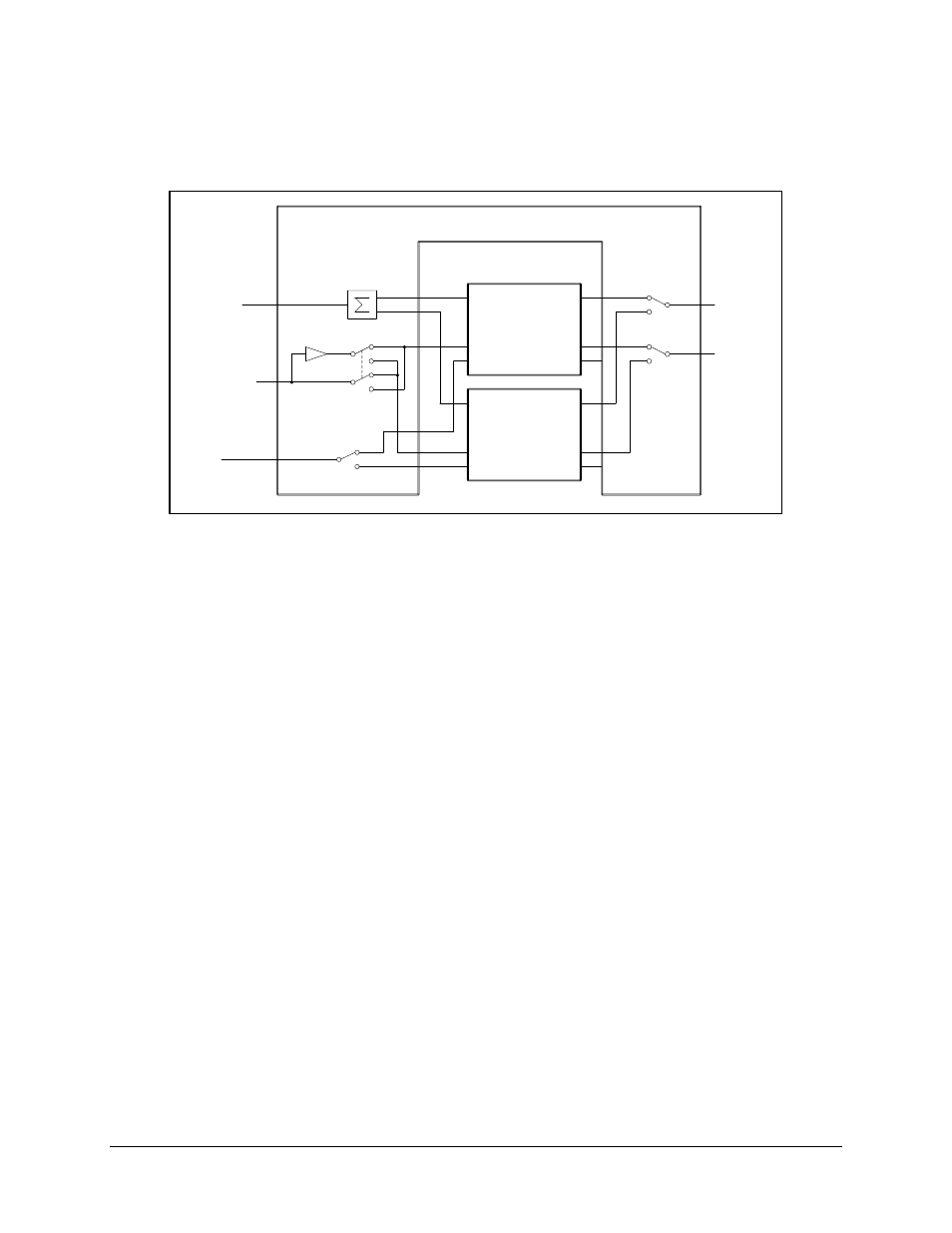
The system block diagram (Figure 1-5) shows how the switch provides the interface
between the prime modem and the terminal and IF converter equipment.
SMS-451E
TX IF
TX IF
SDM-9000
RX IF
RX IF
TX TER
ESC
ECL INTERFACE
RX TER
FAULT
RX TER
RX DATA
RX CLOCK
RX SYNC
ECL INTERFACE
TX IF
SDM-9000
RX IF
TX DATA
TX CLOCK
TX SYNC
TX TER
2 AUDIO
4 BW ALARM
ESC
TX TER
ESC
RX TER
FAULT
Figure 1-5. SMS-451E Block Diagram with SDM-9000 Satellite Modem
Connection of the SMS-451E with the SDM-2020 Modulator and/or Demodulator with a
HSSI Interface along with a Cisco router and test translator is shown in Figure 1-6. The
Y-cables between the modem and switch are provided. The cable between the switch and
the router is ordered separately.