Remote interface (j5), 1 remote interface (j5) – Comtech EF Data SMS-451 User Manual
Page 33
SMS-451 Satellite Switch
Revision 0
Installation
MN/SMS451.IOM
2-7
2.3.1.1
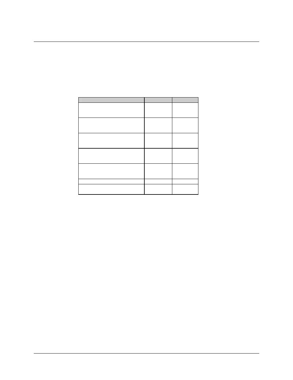
Remote Interface (J5)
The remote interface is provided on a 25-pin female D connector. The remote interface
connector provides remote control and online/offline status of the switch.
The Local/Remote switch on the front panel must be in the Remote mode in order to
control from this input. Status is available regardless of the position of the Local/Remote
switch. Screw locks are provided for mechanical security of the mating connector.
Signal Function
Name
Pin #
DEMOD SWITCH STATUS
NO(B)
NC(A)
COM
8
7
15
MOD SWITCH STATUS
NO(B)
NC(A)
COM
6
5
13
CONTROL MOD REMOTE
MR(A)
MR(B)
GND
4
3
14
CONTROL DEMOD REMOTE
DR(A)
DR(B)
GND
2
1
9
MODE STATUS
COM
18
LOCAL NO
16
REMOTE NC
17
GROUND GND
24
NO CONNECTION
---
19, 20, 21,
22, 23
Note: A closure between the “COM” and “NC” indicates that the “A” unit is online.
An external connection between “GND” and “MR(A)” will force the “A” modulator
online.