2 installation – Comtech EF Data UB-54 User Manual
Page 16
Installation
UB-54 Breakout Panel
2–2
Rev. 1
2.2 Installation
The breakout panel arrives fully assembled from the factory. Install the breakout panel as
follows:
1. Position the breakout panel in the rack.
2. Secure the breakout panel to the rack using 10-32 screws.
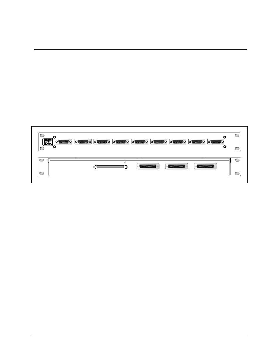
3. Connect the cables to the front and/or rear panel (refer to Figure 2-1). Refer to
Section 2.3 for connector pinout, placement, and function.
TRIB 1 DATA
TRIB 2 DATA
TRIB 3 DATA
TRIB 4 DATA
TRIB 5 DATA
TRIB 6 DATA
TRIB 7 DATA
TRIB 8 DATA
AUX
J9
J8
J7
J4
J1
J2
J3
J5
J6
MUX / DEMUX
BREAKOUT
UB-54
RX AGGREGATE
DEMUX T1-4
DEMUX T5-8
J12
J13
J11
J10
MUX DATA
Figure 2-1. UB-54 Front and Rear Views
Note: One UB-54 breakout panel can be used with a multiplexer or a demultiplexer,
but not both at the same time.
4. (Used with a Multiplexer only) Connect breakout panel to the SDM-300 Satellite
Modem using a 100-pin ribbon cable conforming to Table 2-12, (Comtech
EFData Part No. CA/90101G100-3 or equivalent) as shown in Figure 2-2.