Comtech EF Data SMS-7000 User Manual
Page 140
Advertising
M-2000-Multiplexer Utilization
SMS-7000 Modem Protection Switch
B–2
Rev. 3
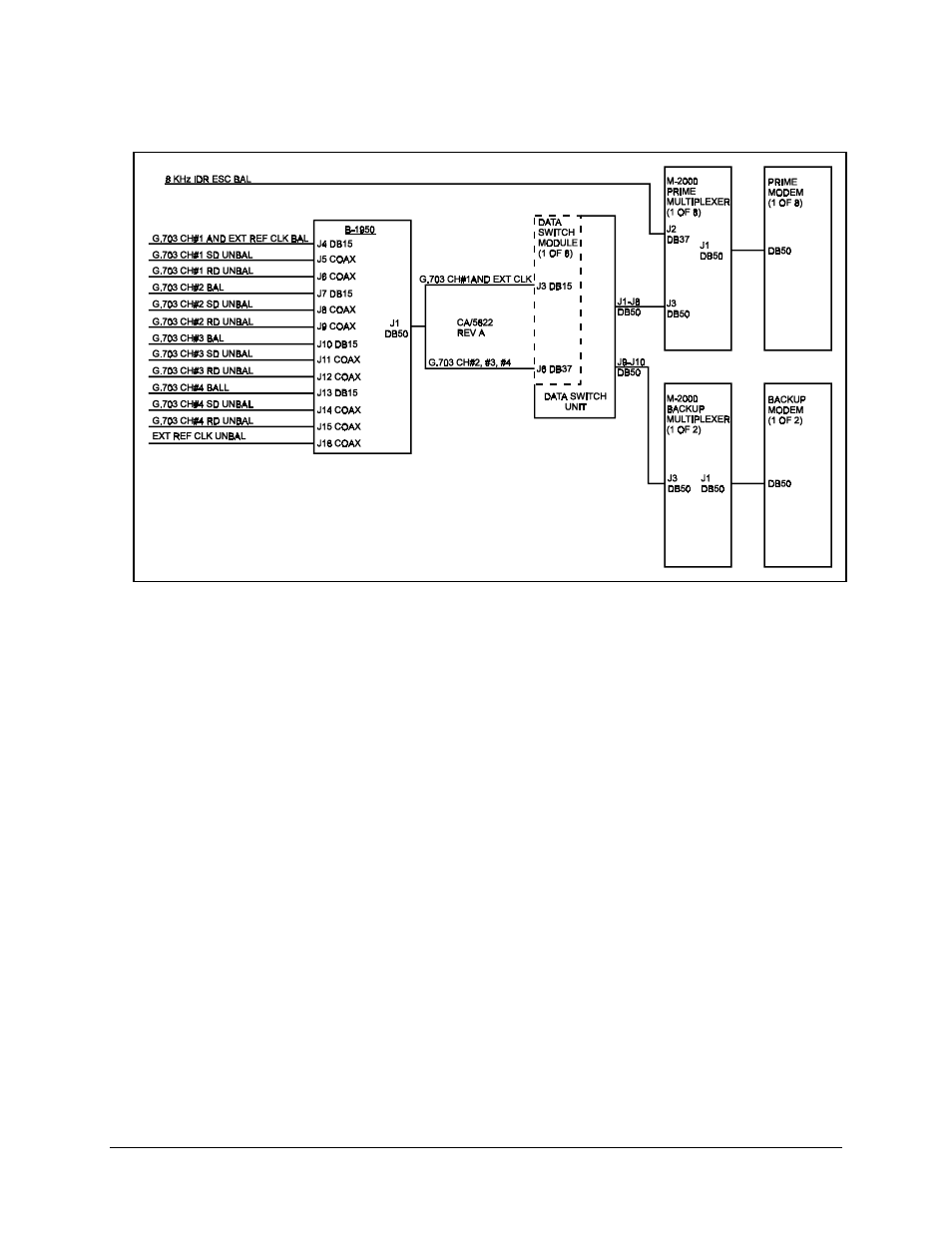
Figure B-1. Terrestrial Data Interconnections
Refer to Table B-1 for signal pinout information on the data switch module J6 connector
equipped with a MUX.
Note: The 8 kbit/s IDR overhead data channel can be directly connected to the prime
multiplexer. The 8 kbit/s overhead will not be switched to the backup in the event of a
prime modem and/or multiplexer failure.
Connect all multiplexers via Remote port (J5) to Modem Remote (J2) on the switch
M&C with an EIA-485 2-wire cable. All multiplexers must be configured for EIA-485
(2-wire), 9600 or 19200 baud with a unique address. Refer to the M-2000 Multiplexer
Installation and Operation Manual for further information on the MUX.
Advertising