Table 2-6 – Comtech EF Data SDM-300L User Manual
Page 32
Advertising
SDM-300L Satellite Modem
Installation
Rev. 2
2–11
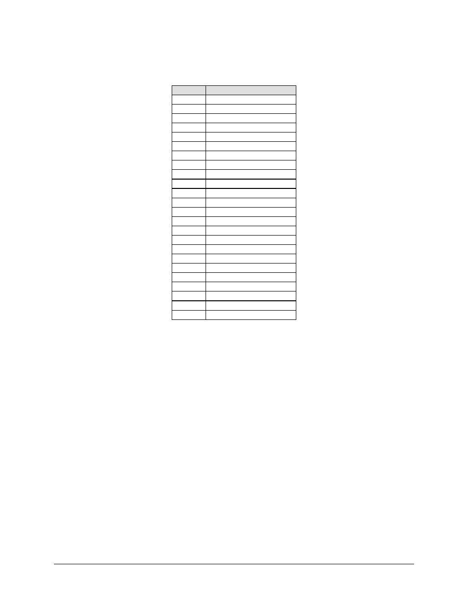
Table 2-6. 37-Pin Connector Pinouts (Optional)
Pin #
EIA-422/MIL-188-144
1, 19
Shield
3 MF
4 SD-A
5 ST-A
6 RD-A
7 RS-A
8 RT-A
9 CS-A
11 DM-A
13 RR-A
16 MC-A
17 TT-A
20, 37
SIGGND
21 DF
22 SD+B
23 ST+B
24 RD+B
25 RS+B
26 RT+B
27 CS+B
29 DM+B
31 RR+B
34 MC+B
35 TT+B
There are jumpers on the PL/6031 EIA-422 interface. Place the jumpers on the center pin
and the pin towards the Master Clock (MC) to allow an external clock input on pins 16
and 34.
If desired, place the jumpers on the TR side to allow an external clock input on pins 12
and 30. Place the jumpers on the TR side for Demand Assigned Multiple Access
(DAMA) applications.
Advertising