2 installation, 3 operation – Comtech EF Data MBT-4000 User Manual
Page 26
MBT-4000 Multi-Band Transceiver System
Revision 4
Installation
MN/MBT4000.IOM
2–2
2.2
Installation
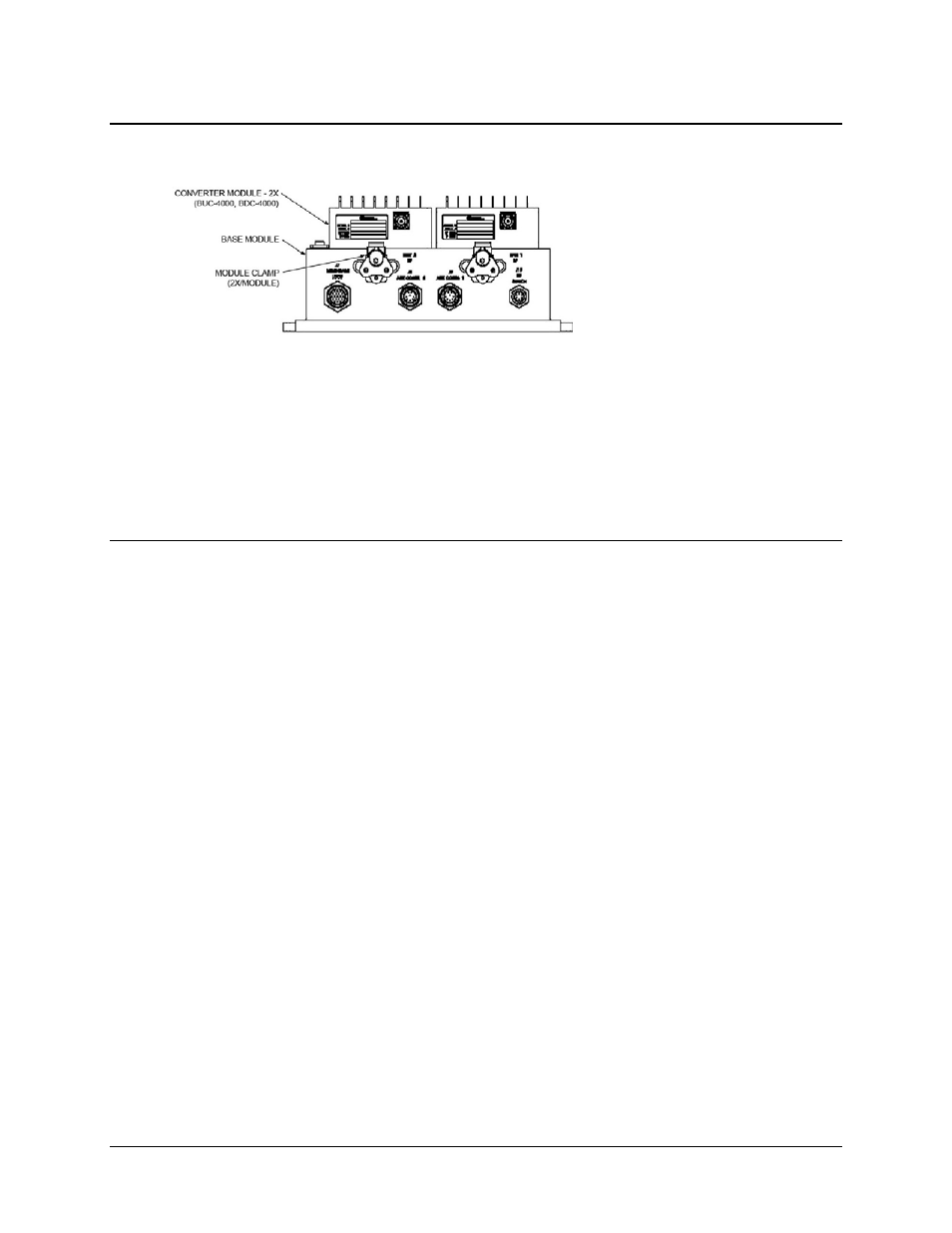
The Base Module for the MBT-4000
system – which provides the M&C,
Power Supply, and Reference
interfaces – may be located near or
on the antenna. Guide pins and
mechanical clamps keep the band-
specific BUC and BDC modules in
place on top of the Base Module.
Cables to the antenna and IDU complete the installation. For complete information on the
MBT-4000’s connectors, including the pinout tables, refer to Chapter 3. EXTERNAL
CONNECTORS.
To change the band of operation, the cables to the BUC/BDC modules are disconnected and the
modules are unlatched from the Base unit, allowing removal and replacement of the existing
modules with appropriate band-specific modules.
2.3
Operation
Once all pertinent connections have been made between the MBT-4000 and other equipment,
refer to Chapter 4. SYSTEM OPERATING PARAMETERS for further information.