6 single-thread kst 2000b system – Comtech EF Data KST-2000A/B User Manual
Page 22
Ku- Band Satellite Transceiver
Revision 9
Introduction
MN/KST2000AB.IOM
1–8
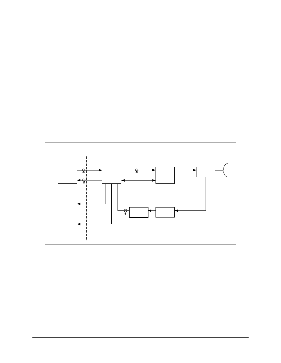
1.1.6 Single-Thread KST-2000B System
A block diagram of the KST-2000B, single-thread Ku-Band system is shown in
Figure 1-4. The operation of KST-2000B system is identical to the KST-2000A system
described in section 1.1.3 except in the receive (downlink) portion.
With the KST-2000B system, a LNB replaces the LNA and the block down converter
from Ku-Band to L-Band in the converter unit. In this configuration, the LNB sets the
received frequency range. The LNB to converter cable carries the LNB’s L-Band output,
LNB prime power (+15 VDC) and a 10 MHz reference signal from the converter to the
LNB.
Indoor Units
(Reference Only)
Modem
Remote
M&C
OMT
TRF
HPA
Converter
Unit
TX
RX
TX
M&C (Power)
Ku-Band
LNB
Ku-Band
L-Band
RX Monitor
Reference Only
70 or 140 MHz
Antenna
L-Band,
DC Power &
10 MHz Ref.
Ku-Band
Figure 1-4. Single Thread KST-2000B Block Diagram