2 j12 | l-band in, 3 j9 | aux comm – Comtech EF Data MBT-4000B User Manual
Page 33
MBT-4000B Multi-Band Transceiver System
Revision 1
External Connectors
MN/MBT4000B.IOM
3–9
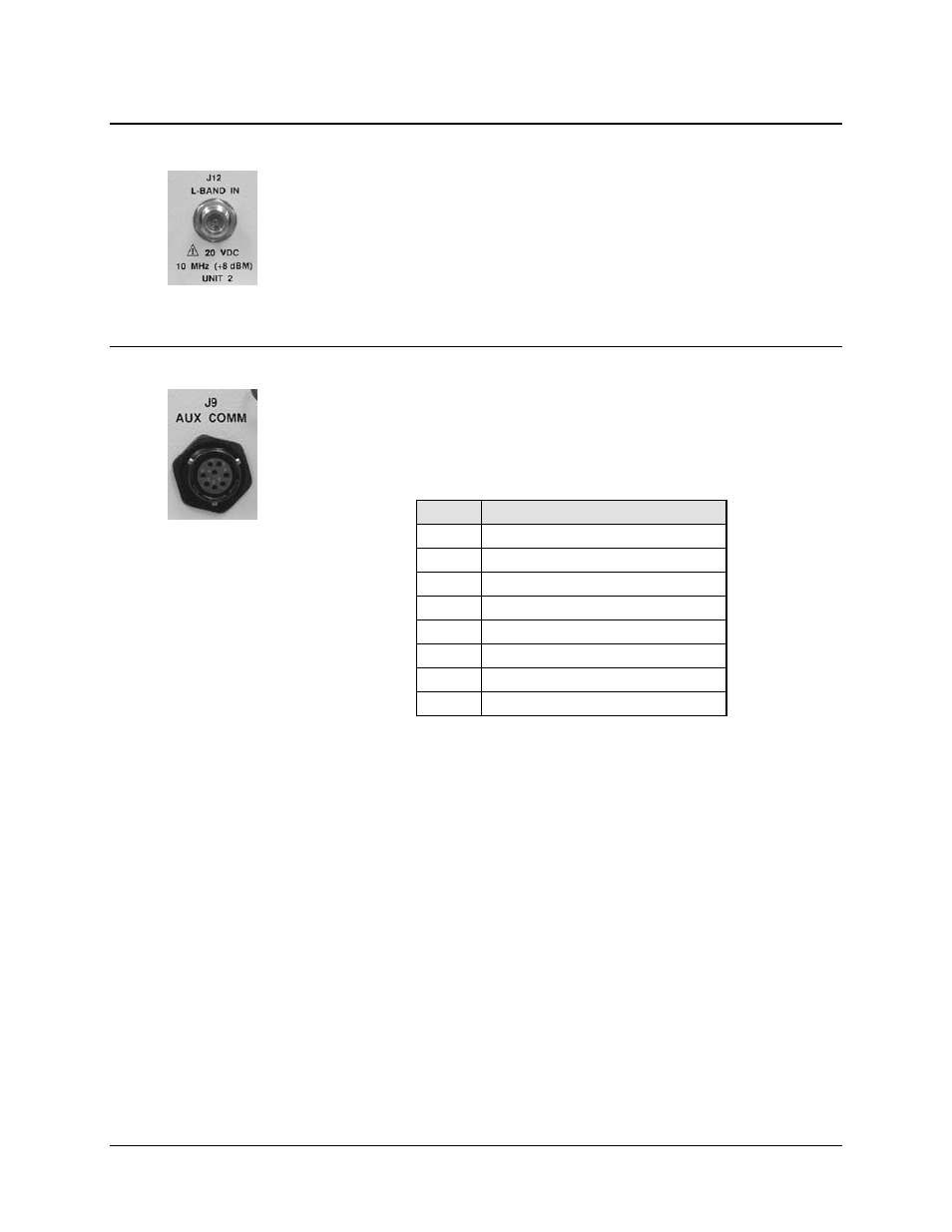
3.2.2.2 J12 | L-BAND IN
Use the J12 | L-BAND IN Type ‘N’ female connector to provide the down
converted IF Input (via a low-noise block down converter (LNB)) to the
MBT-4000B Base Module.
3.2.2.3 J9 | AUX COMM
Use the J9 | AUX COMM 8-pin circular connector to connect a Solid-State Power
Amplifier (SSPA) to the MBT-4000B Base Module.
Table 3-8. J9 | AUX COMM Connector Pinouts
Pin
Signal
A
AUX Rx (+)A
B
AUX Rx (–)A
C
AUX Tx (+)A
D
AUX Tx (-)A
E
+12.6V LNA A
F
IO1 A / Fault (Note 2)
G
IO1 B (Note 3)
H
GND
NOTES:
1. Mating Connector:
CEFD P/N CN/MS3116J12-8P
(Cannon MS3116J12-8P)
2. Input from external amplifier.
3. Normally an input; when programmed as an
output, this pin indicates Unit 1 Online/Offline
status.