4 j10 | rf switch, 5 j5 | rf out (buc-4000 only) – Comtech EF Data MBT-4000B User Manual
Page 34
Advertising
MBT-4000B Multi-Band Transceiver System
Revision 1
External Connectors
MN/MBT4000B.IOM
3–10
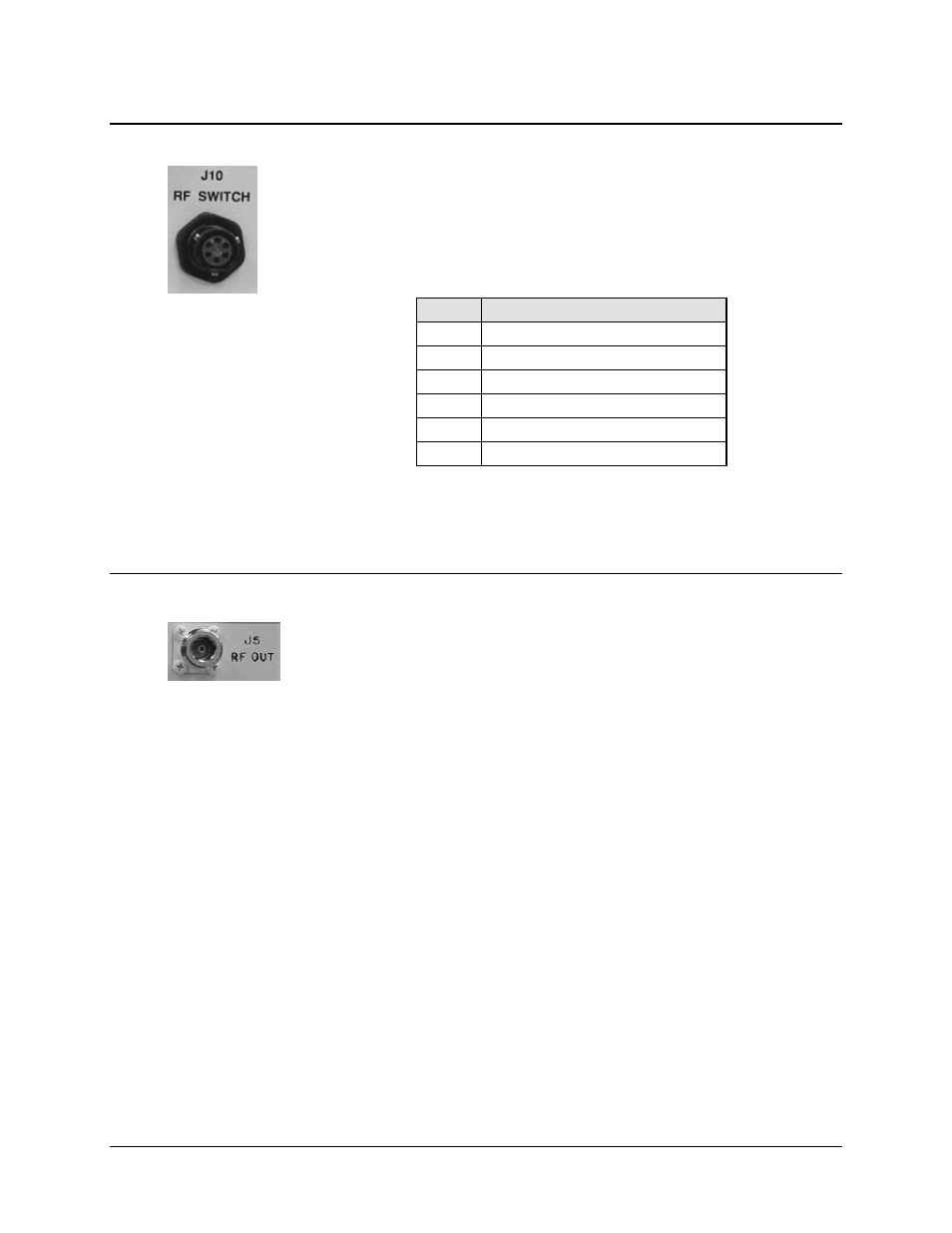
3.2.2.4 J10 | RF SWITCH
Use the J10 | RF SWITCH 6-pin circular connector to connect an RF Switch in a 1:1
configuration (e.g., connecting to two LNBs or SSPAs) to the MBT-4000B Base
Module.
Table 3-9. J10 | RF SWITCH Connector Pinouts
3.2.2.5 J5 | RF OUT (BUC-4000 ONLY)
Use the J5 | RF OUT Type ‘N’ female connector, located on the BUC-4000 Block
Up Converter Module, to provide the upconverted RF Output to an SSPA.
Pin
Signal
A
POS 1 RF
B
GND
C
POS 2 RF
D
POS 1 IND RF
E
GND
F
POS 2 IND RF
NOTE – Mating Connector:
CEFD P/N CN/MS3116J10-6P
(Cannon MS3116J10-6P
Advertising