Comtech EF Data UT-4579 User Manual
Page 18
Advertising
UT4579 X-Band Up Converter
MN/UT4579.IOM
Introduction
Rev. 0
2
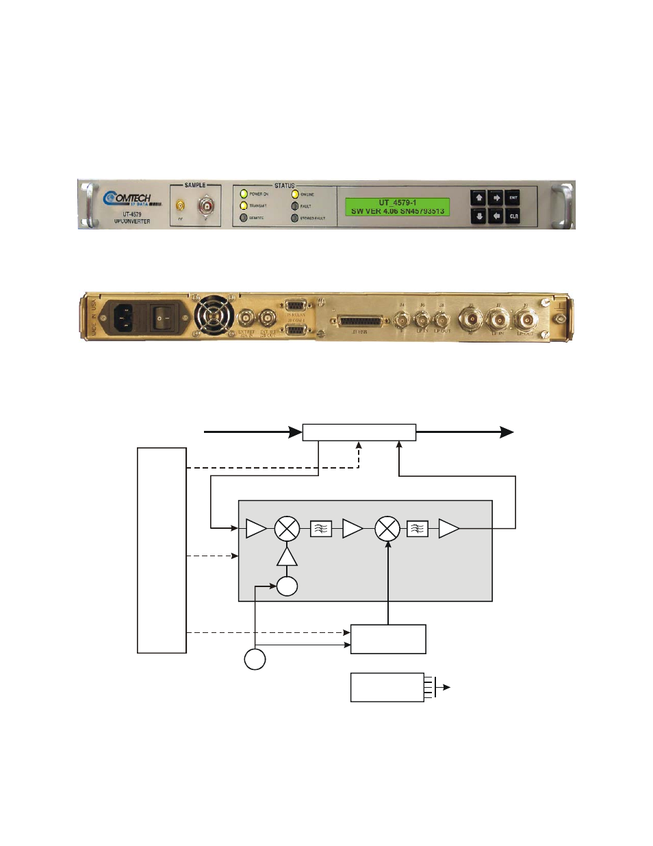
All operator controls, indicators and displays for local and remote operation are located
on the front panel of the converter. Connectors for the external interface connections
(Figure 2) are located on the rear of the converter chassis. A block diagram
(Figure 3) is provided to assist the technician in the operation of the converter.
Figure 1. Front Panel
Figure 2. Rear Panel (shown with TSM Module)
5/10 MHz
REF. OSC.
IF INPUT
(70 or 140 MHz)
RF OUTPUT
(7900-8400 MHz)
MONITOR
&
CONTROL
POWER
SUPPLY
OSC
SYNTHESIZER
I/O MODULE
CONVERTER
SIGNAL PATH
MODULE
OSC
Figure 3. Typical Converter Functional Block Diagram (Model UT-4579 shown)
Advertising