2 system assembly example and cable connections – Comtech EF Data PCB-4300 User Manual
Page 32
Advertising
PCB-4300 1:2 Phase Combiner
Revision 2
Operation and Adjustment Procedures MN/PCB4300.IOM
3–2
3.2
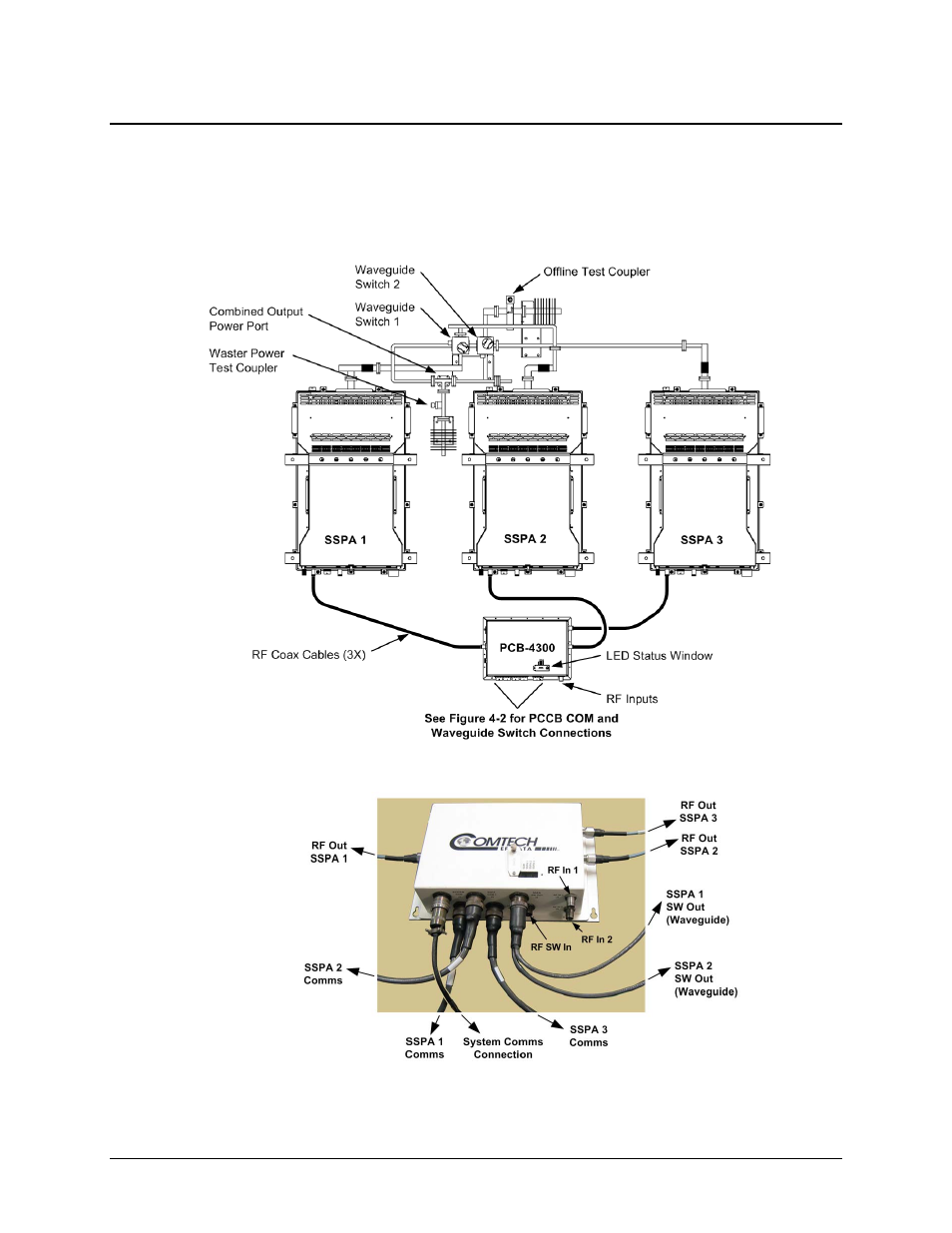
System Assembly Example and Cable Connections
Figure 3-1 shows an example of the PCB-4300 deployed in a typical 1:2 phase combined system
(see Appendix A. ASSEMBLY KITS for details on band-specific system applications). Take note
of the callouts in this figure, as they will be referenced in the procedures that follow in this chapter.
Figure 3-2 summarizes the cabling required from the PCCB to other components of the system.
Figure 3-1. PCB-4300 1:2 Phase Combined System Assembly Example
Figure 3-2. PCB-4300 1:2 Phase Combined System Cable Connections
Advertising