Modem, Modem -12, Figure 26 – Daktronics AF-3150-20-R,A User Manual
Page 32
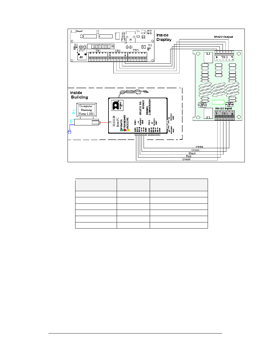
Figure 26: Signal Converter to Surge Suppresser in Display
Signal Converter to Surge Suppressor Board
Signal Converter
(J4 or J5)
Wire Color
Surge Board Assembly
(TB1)
Pin 1 (GND)
Shield
Pin 1 (N.C.)
Pin 2 (RX-P)
Red
Pin 2 (TX-P)
Pin 3 (RX-N)
Black
Pin 3 (TX-N)
Pin 4 (TX-P
Green
Pin 4 (RX-P)
Pin 5 (TX-N)
White
Pin 5 (RX-N)
Pin 6 (GND)
Pin 6 (N.C.)
Modem
Reference Drawings:
System Riser Diagram, Modem .................................. Drawing A-174342
Schematic, Internal, W/Quick Connect........................ Drawing B-177662
A modem-controlled display requires the use of an internal or external modem at the
computer. The local phone company must provide a dedicated phone line to the
display and identify the colors used by the Tip wire and the Ring wire. The telephone
cable is run to the modem board in the display or is connected to a junction box with
a quick connect plug that connects to the display. The phone cable must be routed
though conduit. Do not run signal and display power through the same conduit.
Refer to
and Drawing A-174342 for the system layout.
Electrical Installation
3-12