Figure 31: radio display layout, Figure 32: radio client connection – Daktronics AF-3150-20-R,A User Manual
Page 36
Advertising
exceed 1000 feet. Refer to the Venus 1500 Radio Manual, ED13932, for J-
box and Server connections.
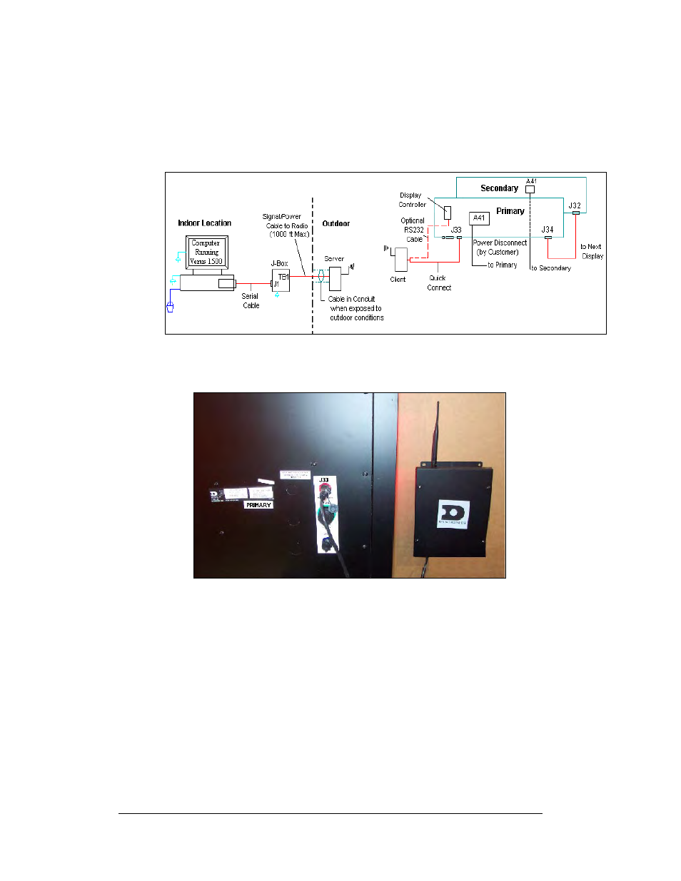
3. Using the quick connect cable, as shown in
, connect from the
Client radio to the RS232 top jack (J33) on the back of the primary display.
(Secure any additional cable to prevent it from being pulled loose by
weather or vandalism.)
Figure 31: Radio Display Layout
Figure 32: Radio Client Connection
Electrical Installation
3-16
Advertising
This manual is related to the following products: