Delta Dore PACK DELTA 600 User Manual
Delta 600, Characteristics, Installation
Characteristics
DELTA 600 is made up of a receiver unit and a technical control unit.
Installation
Positioning options
The receiver must be placed in a high position.
The receiver antenna must be kept away from
conductors (electrical cables, electrical switchboard,
metallic surface).
Mountings
To mount the unit on the wall, it must be separated from its base.
To do this, unscrew the clamp screw as shown opposite.
Once separated from the unit, the base must be fixed to the wall with screws and plugs or
on a flush-mounted box (distance between centres 60 mm) using the holes labelled
➊
.
To do this:
Unscrew the screw
➋
to remove the terminal box cover
➎
.
Temporary partitions, labelled
➌
, are provided
to make room for the connection wire if needed.
- Connect the connection wires (see section 3).
- Replace the terminal box cover and secure it with
the screw
➋
.
Position the unit on the support by first inserting the tabs
➍
, then by pushing it until it is
securely fastened to the support.
3.5 Mounting the antenna
Slide the flexible wire into the tube, then push the tube in
as far as it will go.
Technical unit
• 230 V, 50 Hz power supply, ±10%
• Class II insulation
• Power consumption: 4 VA
• 6 power-supplied operating contact output, 1A,
250V (valves)
• 1 auxiliary contact output, 5 A, 250 V
(burner, circulator, etc.)
• 1 fixed-wire connection bus with the receiver unit
(DELTA 600 BR)
• Dimensions: 80 x 230 x 65 mm
Receiver unit
• TBTS 24 Volt power supply provided by the
technical unit
• Fixed-wire connection bus with the technical unit
(SYT 6/10-type 2 pair telephone cable with shield
and continuity wire, 5 metres max.)
• Receiver frequency: 868 MHz (standard 300 220)
• Radio range 100 to 300 metres outside depending
on the linked equipment (the range can be altered
depending on the installation conditions and the
electromagnetic environment)
• Flexible antenna that slides into its support
• 2 buttons to configure outputs
• Wall mounted
• Dimensions: 128 x 85 x 31 mm
• Protection index: IP 30
• Operating temperature: 0 to +40°C
• Storage temperature: -10 to +70°C
1
2
2700621 Rev.3
Connections
Switch off the mains power before
handling the device.
3
2
4
5
3
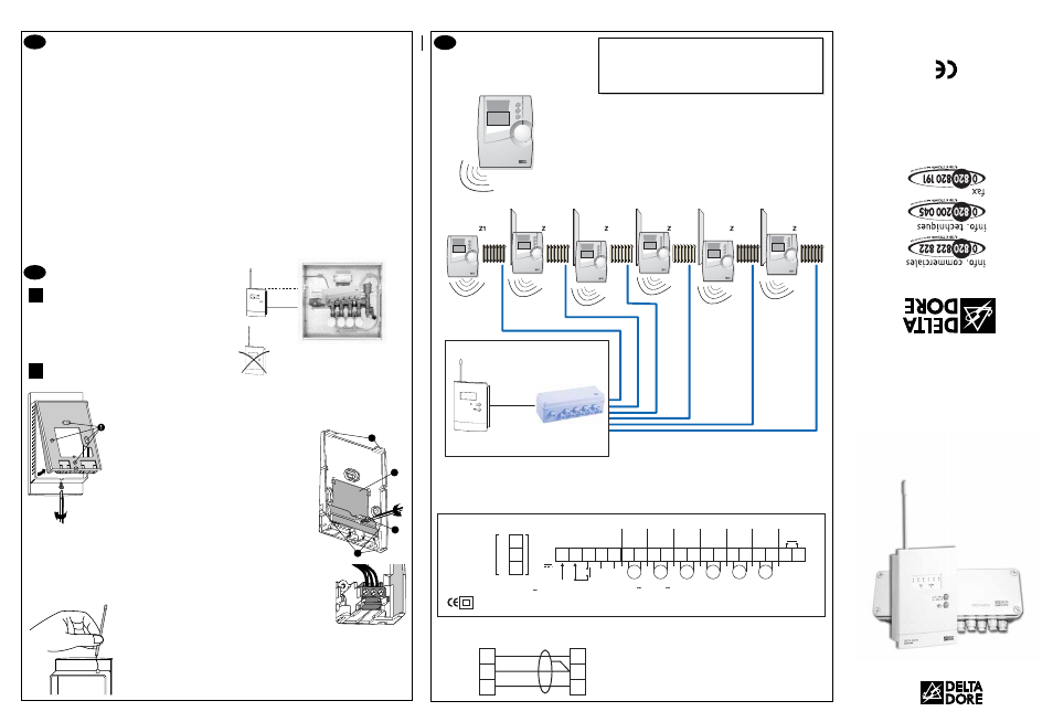
The diagrams provided are simplified for greater clarity.
The protective devices and other accessories required by the standards are
not illustrated.
- Standard UTE C15-100 and good practice must be complied with.
- Connected or nearby equipment must not generate excessive
interference (directive 89/336/EEC).
2
3
4
5
6
Delta 600 TH
Transmitters
Delta 600 TH
Transmitters
Solenoid
valve control
Option 1
Centralized
control
Delta 600 COM
1
6
....
ZS
1
2
OK
ZS
3
4
5
6
Receiver unit
Technical unit
Delta 600
Programming
zone
Programming
zone
Programming
zone
Programming
zone
Programming
zone
Programming
zone
YES
NO
Receiver
Power supply 230V
4VA
50Hz / 60 Hz
BUS
7 8
5
4
6
9 10 11 12 13 14 15 16 17 18 19 20 21 22
Auxiliary
contact
(Burner,
circulator,
etc.)
Valve
power supply
Change-over
24 V to 230 V
V1
V2
V3
V4
V5
V6
1 A
Max.
1 A
Max.
1 A
Max.
1 A
Max.
1 A
Max.
1 A
Max.
5 A
Max.
To
receiver
unit
N
8
7
6
1
2
3
2721159 Re
v.
2
24V
L
Technical unit connecting terminal box
Connection between the receiver unit and the technical unit
8
7
6
1
2
3
Technical
unit
Receiver
unit
Fixed-wire connection bus (SYT 6/10-type 2 pair
telephone cable with shield and continuity wire,
5 metres max.)
The continuity wire is connected to terminal 2 of
the technical unit.
DELTA
DORE TA
LCO - Bonnemain - 352
70 COMB
OURG
E-mail : deltadore@delt
adore.com
pro.deltadore.com
Product compliant with the requirements of directives
89/336/EEC (electromagnetic compatibility) and 73/23/EEC
modified 93/68/EEC (low voltage)
DELTA 600
Control receiver for 6-channel
heating/air-conditioning
control system