Introduction, Set up and connection – Dove Systems MTX-DE 48 User Manual
Page 2
2
INTRODUCTION
The MTX-DE decodes a multiplexed control signal into a DC voltage to drive standard analog dim-
mers from any controller which is compatible with DMX-512 control. Each unit decodes 48 channels
and the starting channel may be set to be any dimmer, 1 to 512. The MTX-DE is factory set to start
on dimmer #1 and the control output voltage is set for 0 to +10V but can be adjusted up to +28.
SET UP AND CONNECTION
INPUT AND OUTPUT
The MTX-DE is usually located close to the dimmer packs it controls. The input and output connec-
tions should be made before the decoder is plugged into power and energized. The circuit card is fac-
tory set for 120VAC 50/60Hz power input; move the line voltage select jumper at J23 to set the line
voltage for 240V.
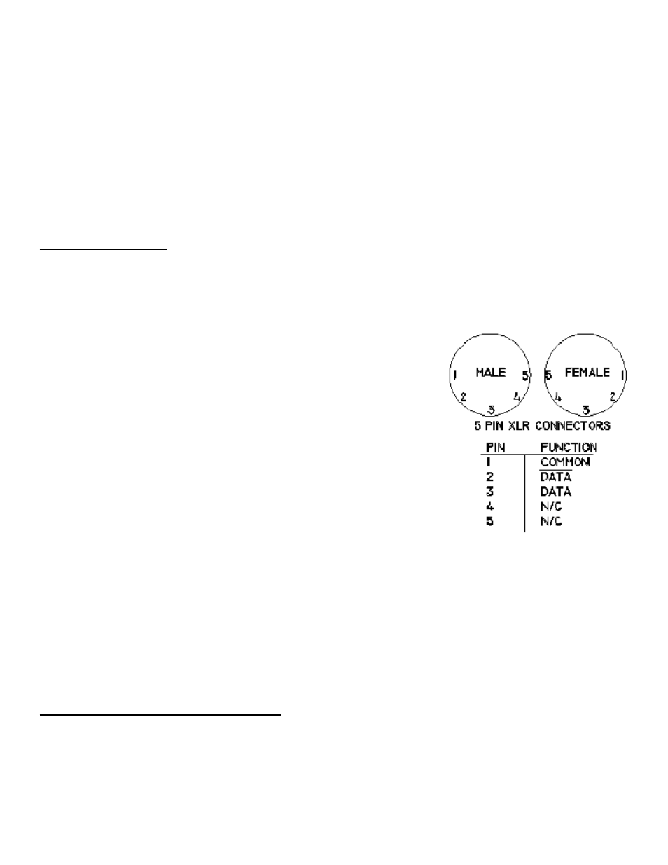
The DMX input is made at the male XLR connector. The signal loops
through on the female connector. Always use the loop through con-
nectors to link equipment in series; do not split the DMX signal with-
out one of the specialty interfaces for this purpose.
Connector pin designations are as shown in the right hand figure;
pins 4 and 5 are "passed through" with no connection made to these
pins.
There are 48 output positions, one for each dimming channel, and
two common terminals at J19 and J20. Positive voltage (i.e. 0 to
+10VDC) output connections are made on the PC terminal strip near
the middle of the circuit card. Some units may be equipped with neg-
ative (i.e. 0 to -10VDC) outputs, in which case output connections
are made on the PC terminal strip to the rear of the circuit card. There must be a common wire to
each dimmer pack. A variety of rear panel output connectors are available as options.
It is possible to parallel an analog controller as a backup control on the outputs, but only if it has di-
ode protection.
The MTX-DE is factory set for 0 to +10 volts output and to start on channel #1. Higher output volt-
ages are possible: adjust R2 clockwise for voltage ranges up to 0 to +28V or 0 to -28V on negative
voltage units.
STARTING CHANNEL SELECT SWITCH
The starting channel is selected through a pushbutton switch on the front panel. Valid starting chan-
nels range from 001 to 512. When the decoder controls the only dimmers in the system, the starting
channel should be set for 001. When there are two or more decoders in the system, the starting
channel may be set for 001, 049, 097, etc. Although channels may overlap, it is usually desirable to
arrange the system for one dimmer per channel. Dimming channels should not overlap with other
DMX equipment, including strobe lights, moving lights, and foggers.