The dr trimmer/mower cutting cords – DR Power Self-Propelled 6.75 (2004 - September 2010) User Manual
Page 26
22 DR
®
TRIMMER/MOWER
The DR TRIMMER/MOWER Cutting Cords
BEFORE PERFORMING ANY ADJUSTMENT, MAINTENANCE PROCEDURE OR INSPECTION, STOP THE
ENGINE, WAIT FIVE (5) MINUTES TO ALLOW PARTS TO COOL AND DISCONNECT THE SPARK PLUG WIRE,
KEEPING IT AWAY FROM THE SPARK PLUG.
RUNNING THE TRIMMER WITH ONLY ONE CORD INSTALLED, OR CORDS INSTALLED AT OTHER THAN
180 DEGREES APART CAN CAUSE EXCESSIVE VIBRATION AND MAY DAMAGE THE MACHINE.
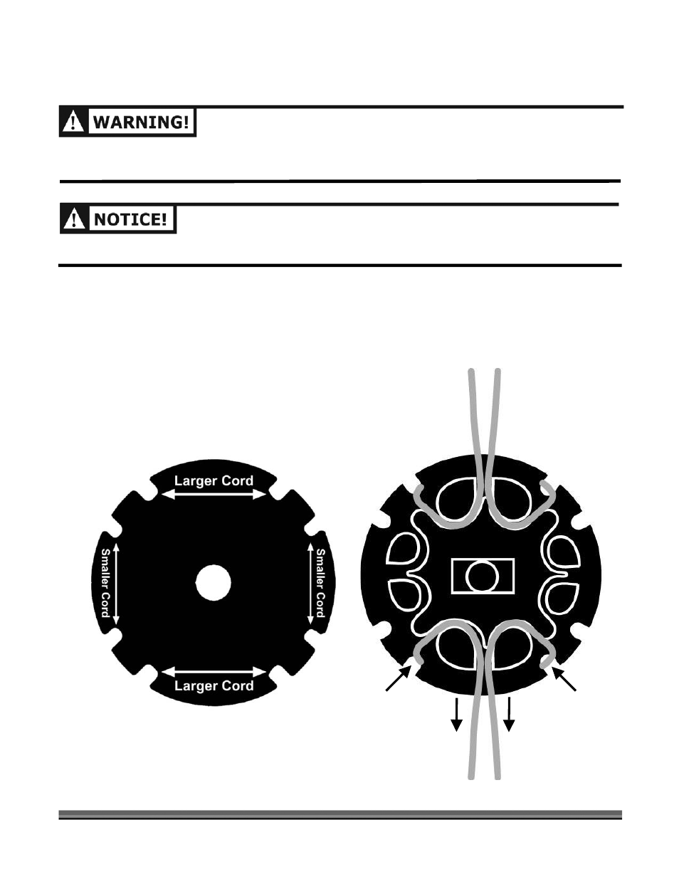
The following figures (Figures 9 and 10) illustrate the Cords installation on the line plates. These figures
show the Line Plates from a cross section point of view. It may look complicated, but once you have done it
a couple of times, it’s easy. There are two (2) sets of installation points on each Line Plate. Each pair is 180
degrees apart. One (1) set of holes is for larger Cord (Blue, 175 mil, and Green, 155 mil) and is marked with
large arrows. The other set of holes is marked with small arrows and are at 90 degrees to the larger holes
and they accommodate the smaller Cord (Orange, 130 mil). Always install two (2) Cords, one opposite the
other.
Figure 9
In Here
Out Here
Out Here
In Here
Figure 10