DR Power Dual Action 3 pt. Hitch Model (Aug 2011 - Present) User Manual
Page 9
CONTACT US AT www.DRpower.com 9
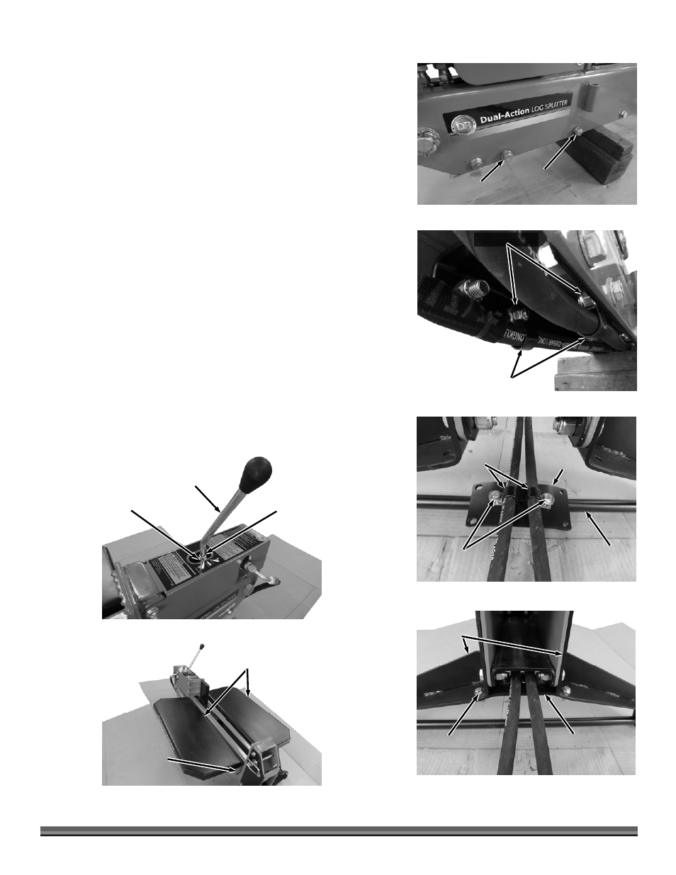
10. Block the front end of the Beam Assembly up to gain access to the hardware
and remove and discard the second set of hardware on each side (Figure 8).
Tighten the third set on each side using a 3/4" Wrench.
11. Place a Hose Clamp over each Hose and attach the Clamp to the Beam with
3/8" Bolts, Washers (one on bolt side and one on nut side) and Locknuts
using two 9/16" Wrenches (Figure 9).
12. Route the Hoses down the underside of the Beam to the rear.
13. Place a Hose Clamp around each Hose near the Axle and loosely attach the
Clamps to the Cross Brace with 5/16" Bolts (clamp side) and Washer and
Locknut (bottom side) (Figure 10).
14. Position the Cross Brace onto the Mounting Brackets and secure with four
5/16" Bolts, Washers(one on bolt side and one on nut side), and Locknuts
using two 1/2" Wrenches (Figure 11).
15. Pull the Hoses to take up any sagging under the Beam and tighten the
Clamp hardware using two 1/2" Wrenches.
16. Remove the Nut and Flat Washer from the Control Lever threads and
reinstall the Nut all the way onto the threads (Figure 12).
17. Place the Washer onto the threads and screw the Control Lever into the top
of the Control Valve as far as it will go. Turn it back to the desired position
depending of your preference to split on the right or left side of the splitter.
Tighten the Jam Nut against the Valve to secure the Lever using a 17mm
Wrench.
18. Install the Trays onto the sides of the Beam assembly and secure with the
Hitch Clips (Figure 13).
Tighten
(both sides)
Figure 8
Remove
(both sides)
Hose Clamps
Figure 9
3/8" Hardware
Hose
Clamps
Figure 10
5/16"
Hardware
Cross
Brace
Axle
Mounting
Brackets
Figure 11
5/16" Hardware
(4 Places)
Cross
Brace
Figure 12
Control
Lever
Jam Nut
Flat Washer
Trays
Figure 13
Mounting
Tubes