Indicators and controls – FiberPlex EF2 User Manual
Page 8
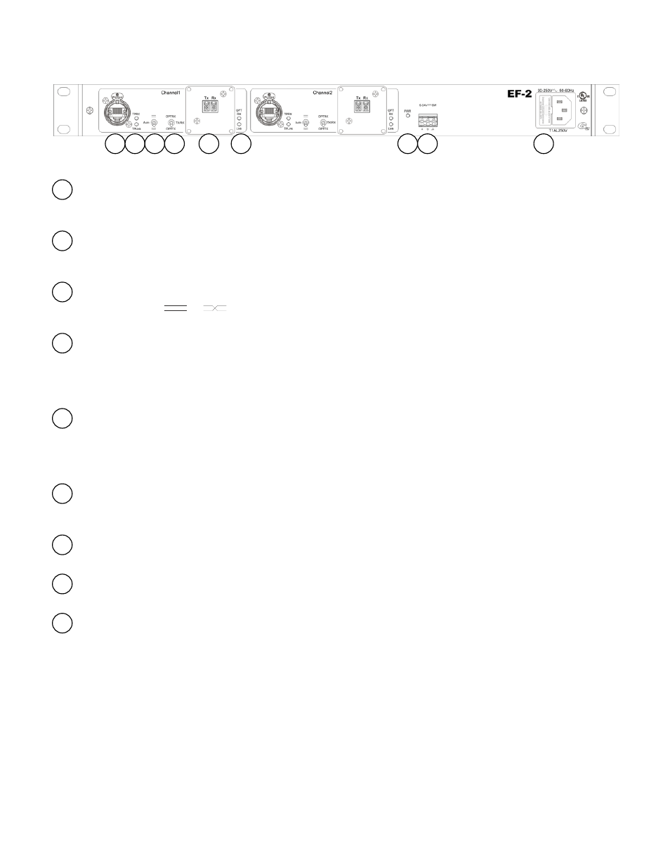
Indicators and Controls
Data connection
The data connection to the EF‐2 is made via a Neutrik™ Ethercon RJ‐45 connector. It uses a standard Ethernet pinout which is
configured using the Polarity Switch. See appendix for a detailed pinout.
Data Status LEDs
A Yellow indication on the upper LED marked “TP RX” indicates that receive data is being detected on the twisted pair. The lower LED
indicates the Link status on the twisted pair. See appendix for more detail.
Polarity Switch
Setting this switch to
or
sets the pinout of TX and RX to accommodate connection to various devices. With a setting of
“Auto”, the EF‐2 will determine the correct pinouts for the TX and RX. See the appendix for more detail.
Directional Mode Switch
The OPT RX and OPT TX positions are both unidirectional modes. In the OPT RX position, data is received by the fiber optic input and
transmitted out to the RJ‐45 connector. In the OPT TX position data is received by the RJ‐45 connector and transmitted to the fiber
optic output. The TX/RX position is a bidirectional mode which acts as a standard Ethernet connection. See the appendix for more
detail.
Fiber Connections
The EF‐2 comes standard with LC fiber connectors. ST, tactical grade TAC‐4 connectors, or Neutrik™ OpticalCon connectors are available as options. In
live production use, it is recommended to fit the units with LC connectors and utilize the VPL‐11, 12, or 13 panels containing 1, 2, or 3, TAC‐4 panel
mount connectors respectively. TAC‐4JR –LC connectors have LC pigtails which connect with the LC connectors on the EF2. Alternately the TAC‐4FR
connector can be mounted directly on the chassis of the EF2. Always be sure to use appropriate fiber and compatible connectors.
Fiber Status LEDs
A Yellow indication on the upper LED marked “OPT RX” indicates that receive data is being detected on the fiber connection. The lower
LED indicates the Link status on the fiber connection. See appendix for more detail.
Power LED
A green LED indicates the power supply is operating correctly.
DC Power Connector
The EF‐2 can run on 9‐24VDC connected via this connector.
AC Power Connector
The EF‐2 runs on a full range switching power supply. It will accept voltages from 90‐250 VAC. This connector also serves as a fuse
holder. Replace fuse only with a 1 Amp 250V (T1AL250V) slo‐blo fuse.
9
8
7
6
5
4
3
2
1
1
2
3
4
5
6
8
7
9