First Co HBC (X) User Manual
Page 2
PIPING
These units employ a hydronic coil
designed for use with either hot or
chilled water.
All piping must be adequately sized
to meet the design water flow require-
ments as specified for the specific
installation. Piping must be installed
in accordance with all applicable
codes.
The piping connections on the
equipment are not necessarily indica-
tive of the proper supply and return
line sizes. To minimize restrictions
piping design should be kept as
simple as possible.
Caution: Prior to connecting to the
fan coil all external piping must be
purged of debris.
All chilled water piping must be in-
sulated to prevent condensation.
Condensate drain lines must be in-
stalled with adequate slope away
from the unit to assure positive drain-
age. Since the drain pan is located on
the suction side of the blower, a nega-
tive pressure exists at the drain pan.
RHBC and CHBC fan coil units re-
quire a minimum trap of 1-1/2 inches
be provided in the drain line to assure
proper drainage. HBC and PHBC fan
coil units may be located where the
return air space is large enough that a
negative pressure is not present,
however, a trapped condensate line
is recommended in case a negative
condition should occur, the unit would
drain properly.
PIPING PRECAUTIONS
1. Flush all field piping prior to con-
nection to remove all debris.
2. Use wet cotton rags to cool valve
bodies when soldering.
3. Open all valves (mid-way for hand
valves, manually open on motorized
valves) prior to soldering.
4. When soldering to bronze or brass,
heat the piping while in the socket/cup
and begin introducing the solder
when the flux boils rapidly.
Avoid direct flame into the solder joint.
5. Heat can only be applied to the cup
of the valve body for a minimal time
before damage occurs (even with the
use of wet rags.
6. Avoid rapid quenching of solder
joints as this will produce joints of
inferior quality.
7. The valve package will not support
the weight of the connecting pipes. All
pipes which are connected to the
units must be completely supported
prior to connection to the unit.
8. Provisions must be made for ex-
pansion and contraction of piping sys-
tems. All horizontal and vertical ris-
ers, including runouts, must be able to
withstand significant movement with
temperature changes. Failure to do
so will result in damage and failure of
piping, fittings and valves throughout
the building.
9. Never insulate the heads or motor-
ized portion of control valves. Dam-
age can occur in the form of exces-
sive heat build up and interference to
the operation and moving parts will
result.
10. All piping made in the field should
be installed with consideration of ad-
ditional space for any electrical rout-
ing that may be required.
11. Connect all piping per accepted
industry standards and observe all
regulations governing installation of
piping systems. When all connec-
****** WARNING ******
When connecting piping or
valve kits to fan coil units, do
not bend or reposition the coil
header tubing for alignment
purposes. This could cause a
tubing fracture resulting in a
water leak when water pres-
sure is applied to the system.
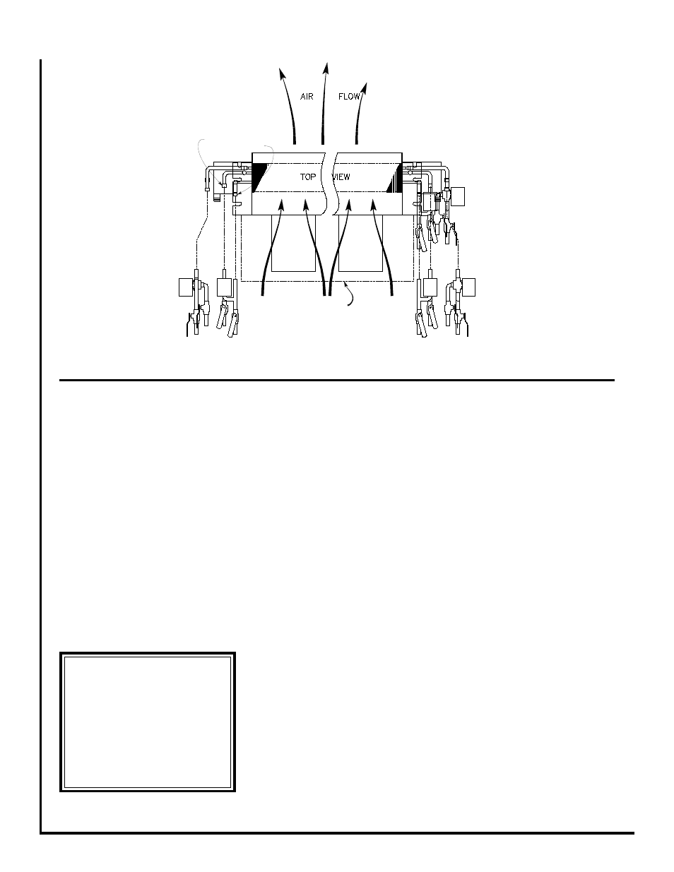
Figure 1 - Determination of Right-hand/Left-hand References
Left Hand Arrangement
Return Connection
Supply Connection
Right Hand Arrangement
Plenum
(Optional)
A
A
A
B