Flowserve WDX User Manual
Page 19
WDX USER INSTRUCTIONS ENGLISH 71576322 06-05
Page 19 of 46
®
The table in 4.6.3 summarizes the maximum forces
and moments allowed on WDX pump casings. Refer
to Flowserve for other configurations.
Ensure piping and fittings are flushed
before use.
Ensure piping for hazardous liquids is arranged
to allow pump flushing before removal of the pump.
Excessive external strains (forces, moments)
may cause misalignment, general vibrations, hot
bearings or excessive wear on couplings and seals.
In extreme cases, leakage may result with potential
loss of life with hot or corrosive liquids.
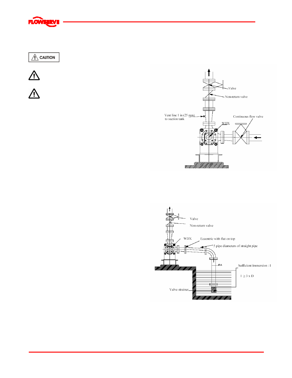
4.6.2 Suction piping
Refer to the diagrams below for typical designs of
suction piping for both flooded suction and suction lift.
a) The inlet pipe should be one or two sizes larger
than the pump inlet bore and pipe bends should
be as large a radius as possible.
b) Pipework reducers should be conical and have a
maximum total angle of divergence of 15 degrees.
c)
Pipework should be arranged to avoid air pockets.
d) If high points cannot be avoided on the suction line
equip them with air relief cocks.
e) On suction lift the piping should be inclined up
towards the pump inlet with eccentric reducers
incorporated to prevent air locks.
f)
On positive suction, the inlet piping must have a
constant fall towards the pump.
g) Flow should enter the pump suction with uniform
flow, to minimize noise and wear. This is
particularly important on large or high-speed
pumps which should have a minimum of five
diameters of straight pipe on the pump suction
between the elbow and inlet flange. See section
10.3, Reference 1, for more detail.
h) Inlet strainers, when used, should have a net `free
area' of at least three times the inlet pipe area.
i)
Do not install elbows at an angle other than
perpendicular to the shaft axis. Elbows parallel to
the shaft axis will cause uneven flow.
j)
Except in unusual circumstances strainers are
not recommended in inlet piping. If considerable
foreign matter is expected a screen installed at
the entrance to the wet well is preferable.
k)
Fitting an isolation valve will allow easier
maintenance.
l)
If an inlet valve is necessary, choose a model
with full bore so as to limit losse s. Valve stem
should be in a vertical position. There should be
a minimum of five pipe diameters between the
pump and the valve.
m) Never throttle pump on suction side and never
place a valve directly on the pump inlet nozzle.
n) Do not tighten flanges before the final check.
Typical design
–flooded suction
Note:
Ideally reduc ers should be limited t o one pipe diameter c hange,
ie 150 mm (6 in.) t o 200 mm (8 in.). Must have a maxi mum t otal
angle of di vergenc e of 15 degrees.
Typical design
–suction lift
Notes:
1. S = Minimum s ubmergenc e >3E.
2. I deally r educ ers to be limited t o one pipe di ameter c hange,
ie 150 mm (6 in.) t o 200 mm (8 in.). Must have a maxi mum t otal
angle of divergence of 15 degrees.