3 initial alignment, 4 piping – Flowserve NMD User Manual
Page 15
NMD, NMAD USER INSTRUCTIONS ENGLISH 71576436 - 11/09
Page 15 of 40
4.3 Initial alignment
Before connecting the couplings
verify the motor rotation direction.
4.3.1 Thermal expansion
The pump and motor will normally
have to be aligned at ambient temperature and
should be corrected to allow for thermal expansion
at operating temperature. In pump installations
involving high liquid temperatures, the unit should be
run at the actual operating temperature, shut down
and the alignment checked immediately.
4.3.2 Alignment methods
Ensure pump and driver are isolated
electrically and the half couplings are disconnected.
Ensure that the pump pipework, suction and
discharge, is disconnected.
The alignment MUST be checked.
Although the pump will have been aligned at the
factory it is most likely that this alignment will have
been disturbed during transportation or handling. If
necessary, align the motor to the pump, not the
pump to the motor.
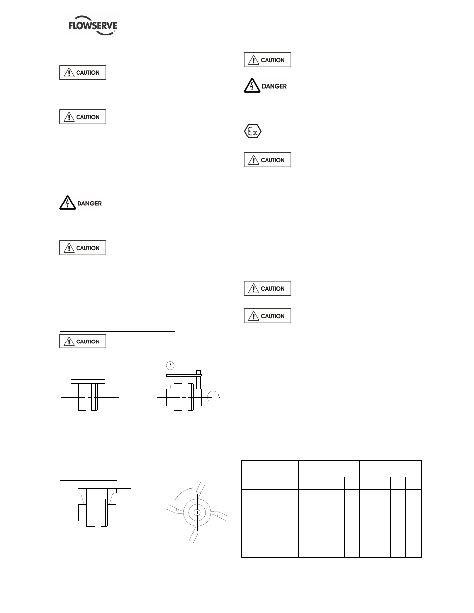
Alignment
Parallelism and concentricity check:
Check the alignment at three or four
points, before pipeworks assembly.
with a rule
with a comparator
Admissible margin for a motor with roller bearings:
= 0.15 mm parallel checking
= 0.1 mm angular checking
Angular checking:
with a sliding rule
with a caliper gauge
The alignment will be definitive only
after pipework connection (see § 4.4.1).
Never connect the electric motor
before the setting has been completely finished.
4.4 Piping
The user must verify that the equipment is
isolated from any external sources of vibration.
Protective covers are fitted to the
pipe connections to prevent foreign bodies entering
during transportation and installation. Ensure that
these covers are removed from the pump before
connecting any pipes.
4.4.1 Suction and discharge pipework
The dimensions of the pipes do not directly depend
on suction and discharge diameters of the pump:
a) First, choose a flow speed < 2 m/s at suction,
and about 3 m/s at discharge.
b) Take into account the available NPSH, which
must be superior to the required NPSH of the
pump.
Never use pump as a support for
piping.
Do not mount expansion joints in
such a way that their force, due to internal pressure,
may act on the pump flange.
Maximum forces and moments allowed on the pump
flanges vary with the pump size and type. These
external strains may cause misalignment, hot
bearings, worn couplings, vibrations and the
possible failure of the pump casing.
When designing the pipes (§ 4.4.2.1, § 4.4.2.2, §
4.4.3.1) take necessary precautions in order not to
exceed maximum allowed strains.
Forces and moments applied to the pump flanges
must never exceed the values shown in the table
below:
Forces (daN)
Moments (m.daN)
Pipework
arragement
D
N
fl
a
n
g
e
s
F
Y
F
Z
F
X
∑
F
M
Y
M
Z
M
X
∑
M
100
50
40
45
80
18
20
25
37
125
62
55
55
100
22
26
31
46
150
75
60
81
120
22
31
37
55
200 100
81
90
157
34
39
48
72
250 125 100 112 195
43
49
60
89
Suction and
discharge
300 150 121 135 235
65
74
91
134