Flowserve NMD User Manual
Page 17
NMD, NMAD USER INSTRUCTIONS ENGLISH 71576436 - 11/09
Page 17 of 40
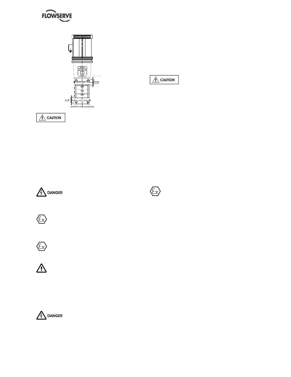
Control
manometer
Do not tighten flanges before the final
check (see § 4.4.4).
4.4.4 Final checks
a) Check the tightening of anchor bolts. Tighten
them if necessary.
b) Check that protective covers on suction and
discharge flanges are removed.
c) Check that holes of pipework flanges are parallel
and correspond to those of the pump.
d) Tighten suction and discharge flanges.
4.5 Electrical connections
Electrical connections must be made
by a qualified Electrician in accordance with relevant
local national and international regulations. This
includes any grounding.
It is important to be aware of the EUROPEAN
DIRECTIVE on potentially explosive areas where
compliance with IEC60079-14 is an additional
requirement for making electrical connections.
Avoid mechanical, hydraulic or electrical overload
by using motor overload trips or a power monitor and
make routine vibration monitoring.
It is important to be aware of the EUROPEAN
DIRECTIVE on electromagnetic compatibility when
wiring up and installing equipment on site. Attention
must be paid to ensure that the techniques used during
wiring/installation do not increase electromagnetic
emissions or decrease the electromagnetic immunity of
the equipment, wiring or any connected devices. If in
any doubt, contact Flowserve for advice.
The motor must be wired up in
accordance with the motor manufacturer's
instructions (normally supplied within the terminal
box) including any temperature, earth leakage,
current and other protective devices as appropriate.
The identification nameplate should be checked to
ensure the power supply is appropriate.
A device to provide emergency stopping shall be
fitted.
Carry out the ground connections according to the
current local regulations.
To avoid any risk of jamming, the
direction of rotation will be checked after priming of
the pump (§ 5.3.1, 5.3.2) and before the first start (§
5.4.2).
4.6 Final shaft alignment check
a) Check the alignment pump-motor according to
the procedure § 4.3.2. Rectify if necessary by
adjusting the motor only.
b) Check by hand that the pump turns freely.
A binding indicates a distortion of the pump,
which is due to excessive pipes strains. If
necessary the pipework design must be re-
examined.
c) If it provided, connect auxiliary pipe systems
(hydraulic, pneumatic, sealing system).
d) Control tightness and functionality of auxiliary
piping.
4.7 Protection systems
The following protection systems are
recommended particularly if the pump is installed in
a potentially explosive area or is handling a
hazardous liquid. If in doubt consult Flowserve. If
there is any possibility of the system allowing the
pump to run against a closed valve or below
minimum continuous safe flow a protection device
should be installed to ensure the temperature of the
liquid does not rise to an unsafe level.
If there are any circumstances in which the system
can allow the pump to run dry, or start up empty, a
power monitor should be fitted to stop the pump or
prevent it from being started. This is particularly
relevant if the pump is handling a flammable liquid.
If leakage of product from the pump or its associated
sealing system can cause a hazard it is
recommended that an appropriate leakage detection
system is installed.
To prevent excessive surface temperatures at
bearings it is recommended that temperature or
vibration monitoring are carried out. See sections
5.5.4 and 5.5.5.
If a defect of cooling can lead to temperature higher
than those acceptable a system of cooling
surveillance must be installed.