Flowserve CPXVC User Manual
Page 13
CPXVC USER INSTRUCTIONS ENGLISH 26999930 03-11
Page 13 of 32
flowserve.com
Maximum forces and moments allowed on the pump
flanges vary with the pump size and type. To minimize
these forces and moments that may, if excessive, cause
misalignment, hot bearings, worn couplings, vibration
and the possible failure of the pump casing, the
following points should be strictly followed:
•
Prevent excessive external pipe load
•
Never draw piping into place by applying force to
pump flange connections
•
Do not mount expansion joints so that their force,
due to internal pressure, acts on the pump flange
4.5.1
Suction and discharge pipework
In order to minimize friction losses and hydraulic
noise in the pipework it is good practice to choose
pipework that is one or two sizes larger than the
pump discharge. Typically main pipework velocities
should not exceed 3 m/s (9 ft/sec) on the discharge.
Never use the pump as a support for
piping.
Ensure piping and fittings are flushed
before use.
Ensure piping for hazardous liquids is arranged
to allow pump flushing before removal of the pump.
4.5.2
Discharge piping
A non-return valve should be located in the discharge
pipework to protect the pump from excessive back
pressure and hence reverse rotation when the unit is
stopped.
Fitting an isolation valve will allow easier maintenance.
4.5.3
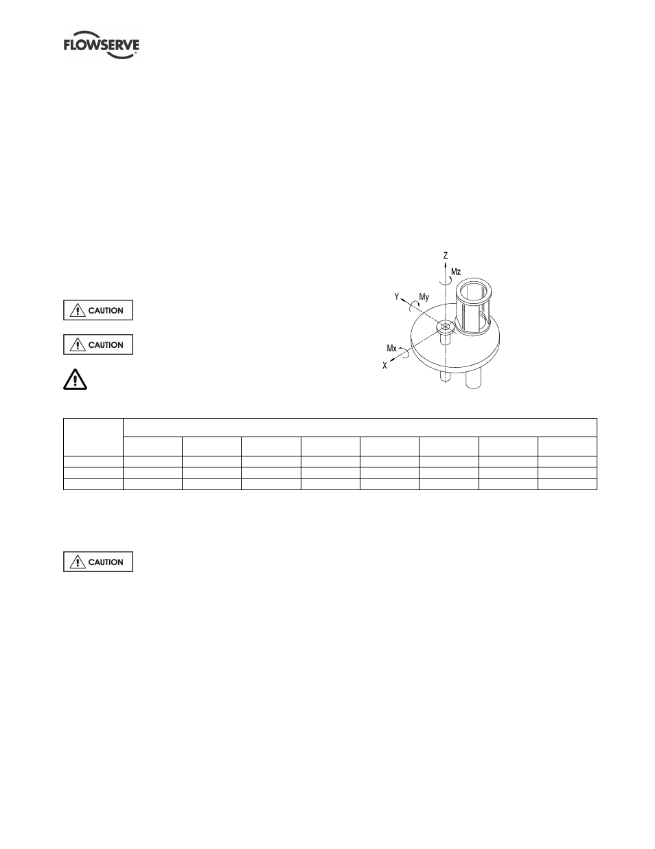
Maximum forces and moments allowed on
the main soleplate discharge flange
The table below uses the sign convention shown for the
pump soleplate discharge flange maximum forces and
moments. These are valid for a pump end up to 100 ºC
(212 ºF) and the soleplate on a rigid foundation.
Maximum forces (F) in kN (lbf) and moments (M) in Nm (lbf•ft)
Discharge
flange size
mm (in.)
Fx
Fy
Fz
Fr
Mx
My
Mz
Mr
50 (2.0)
0.71 (160)
0.58 (130)
0.89 (200)
1.28 (290)
0.46 (340)
0.23 (170)
0.35 (260)
0.62 (460)
80 (3.0)
1.07 (240)
0.89 (200)
1.33 (300)
1.93 (430)
0.95 (700)
0.47 (350)
0.72 (530)
1.28 (950)
100 (4.0)
1.42 (320)
1.16 (260)
1.78 (400)
2.56 (570)
1.33 (980)
0.68 (500)
1.00 (740)
1.80 (1 330)
4.5.4
Auxiliary piping
4.5.4.1
Pumps fitted with a soleplate packed
gland
Ensure lubrication is supplied to the
gland packing.
4.5.4.2
Pumps fitted with mechanical seals
Seal housings/covers having an auxiliary quench
connection require connection to a suitable source of
liquid flow, low pressure steam or static pressure from
a header tank. Recommended pressure is 0.35 bar
(5 psi) or less.
Double seals require a barrier liquid between the
seals, compatible with the pumped liquid.
With back-to-back double seals, the barrier liquid
should be at a minimum pressure of 1 bar (15 psi)
above the maximum pressure on the pump side of
the inner seal. The barrier liquid pressure must not
exceed limitations of the seal on the atmospheric
side. For toxic service the barrier liquid supply and
discharge must be handled safely and in line with
local legislation.
Special seals may require modification to auxiliary
piping described above. Consult Flowserve if unsure
of correct method or arrangement.
4.5.4.3
Pumps fitted with heating jacket
As the pump is constructed as a heated jacketed unit,
steam must be connected to the steam inlet flange and
removed via the steam outlet flange.