Flowserve Twin Screw Rotary User Manual
Page 23
TWIN SCREW PUMPS. ORIGINAL USER INSTRUCTIONS. ENGLISH. 71569243 – 07/10
Page 20 of 53
®
4 INSTALLATION
Equipment operated in hazardous locations
must comply with the relevant explosion protection
regulations. See section 1.6.4 Products used in
potentially explosive atmospheres.
4.1 Location
The pump should be located to allow room for access,
ventilation, maintenance and inspection and should be
as close as practicable to the supply of liquid to be
pumped. There should be ample room to allow the
use of an overhead crane or lifting device with
sufficient capacity to lift the heaviest part of the unit.
Simple suction and discharge piping layouts are
desired. Allow sufficient room to facilitate the back
pull-out feature.
Refer to the general arrangement drawing for the
pump set.
4.2 Part assemblies
Motors may be supplied loose on Twin Screw pumps,
typically on frame sizes 400 and above. It is the
responsibility of the installer to ensure that the motor
is assembled to the pump and lined up as detailed in
section 4.5.2 Alignment methods.
4.3 Foundation
The foundation may consist of any
material that will afford permanent, rigid support to the
full area of the pump or driver supporting member. It
should be of sufficient size and mass to absorb expected
strains and shocks that may be encountered in service.
Concrete foundations built on solid ground are desirable.
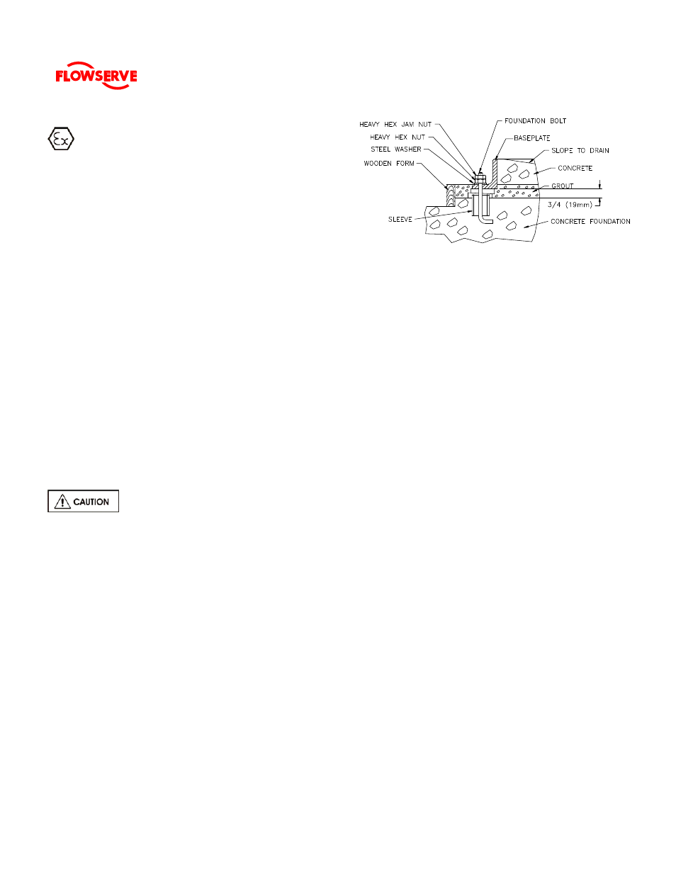
The purpose of foundation bolts is to anchor the pump
unit securely to the foundation such that the foundation
and pump assembly become a single structural unit.
High strength steel foundation bolts (SAE Gr. 5 or equal)
of the specified diameter should be located according to
the elevation drawing provided. Each bolt should be
surrounded by a pipe sleeve two or three times the
diameter of the bolt (see Fig. l). The sleeves should be
securely anchored and designed to allow the bolts to be
moved to conform with the holes in the baseplate. The
bolts should be sufficiently long to allow for wedges or
shims or levelling nuts under the baseplate, and a
washer, heavy hex nut and hex jam nut for retention.
Since baseplate levelling is performed after the
foundation has cured, it is best to use extra long bolts
which can be shortened after the installation is complete.
Figure 1
4.4 Baseplate installation
Position the baseplate and pump next to the foundation
and clean the foundation surface thoroughly. Remove
the rag packing from the pipe sleeves and place wedges
or shims as close to the foundation bolts as possible.
These may be omitted if a jacking nut on the foundation
anchor bolts is preferred for levelling. Initial levelling
should be within 0.75 mm (0.030 inches).
Remove the flange covers and check inside the pump
nozzles for cleanliness. Kerosene is recommended as
the best solvent for removing factory applied rust
preventative. Ensure that all traces of rust preventative
are removed from the discharge and suction flange
faces, the exposed shafting and all coupling surfaces.
Flush the pump internals of any rust preventative applied
for long term storage.
Lift the baseplate assembly, remove the shipping skids
and clean the underside of the baseplate. Position the
baseplate over the foundation and lower the unit over the
foundation bolts and onto the wedges, shims or jacking
nuts.
With the aid of a machinist's level, adjust the wedges,
shims or jacking nuts to level the pump and driver
mounting pads in each direction within .001”/ft of
separation between the equipment mounting pads.
Check to ensure that the suction and discharge flanges
are plumb, level, and at the correct elevation. It is
normal practice to set the mounting pads slightly low in
order to permit lowering of units which may be required
to suit future piping or minor changes. Place washers
over the foundation bolts and install nuts. Tighten finger
tight only.
Check the impeller axial clearance (refer to Section
6
MAINTENANCE
) and that the rotor turns freely by hand.
Note: Grout is not poured until an initial alignment
of the pump and driver has been performed.