4 recommended spares, 5 tools required, 6 fastener torques – Flowserve Mark 3 ISO Durco User Manual
Page 20: 7 setting impeller clearance, 8 disassembly, Clearances, impeller (6.7), Disassembly (6.8), Dismantling (6.8, disassembly), Fastener torques (6.6), Setting impeller clearance (6.7)
DURCO MARK 3 ISO CLOSE COUPLED ENGLISH 26999985 02-14
Page 20 of 32
flowserve.com
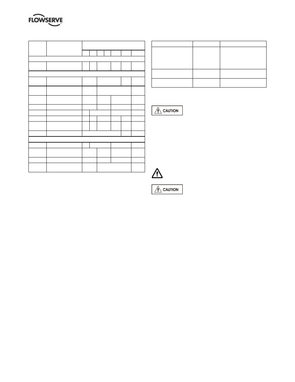
6.4 Recommended spares
Part no. Designation
Number of pumps
(including stand-by)
2
3
4
5
6/7
8/9 10 (+)
For start-up purposes
4590
Pump casing
gasket
4
6
8
9
12
150%
2 to 4 years operation
2200
Integral stub shaft
and impeller
1
2
3
30%
7120
Muff coupling
(halves)
2
4
20%
9906/04
Coupling grub
screw
1
2
3
50%
9951/02 Adjustment stud
1
2
3
50%
4200
Mechanical seals
1
2
3
30%
4300
Lip seal *
4
6
8
9
10
100%
4590
Pump casing
gasket
4
6
8
9
12
150%
8100
Motor
-
1
2
Optional for start-up purposes
4200
Mechanical seals
1
2
3
30%
9906/04
Coupling grub
screw
1
2
3
50%
9951/02 Adjustment stud
1
2
3
50%
7120
Muff coupling
(halves)
2
4
20%
* Where fitted.
6.5 Tools required
A typical range of tools that will be required to
maintain these pumps is listed below.
Readily available in standard tool kits, and dependent
on pump size:
Open ended spanners (wrenches) to suit up to
M 20 screws/nuts
Socket spanners (wrenches), up to M 20 screws
Allen keys, up to 10 mm (A/F)
Range of screwdrivers
Soft mallet
More specialized equipment:
Bearing pullers
Bearing induction heater
Dial test indicator
C-spanner (wrench) - for removing shaft nut.
(If difficulties in sourcing are encountered, consult
Flowserve.)
Tapered seal fitting tools for rubber bellows seals
6.6 Fastener torques
Screw position
Screw size
Torque Nm (lbf·ft)
Casing and
seal cover
M8
M10
M12
M16
M20
16 (12)
25 (18)
35 (26)
80 (59)
130 (96)
Muff coupling
M8
M10
30 (22)
58 (43)
Cartridge seal sleeve
(where applicable)
M5
M8
5.5 (7) *
16 (22) *
* Where a torque wrench is unavailable, slightly tighten the
setscrews to centralize the cartridge seal, then tighten with a T-bar
until a torsional twist between 60 and 90 degrees is achieved. The
torque applied will be approximate to that recommended.
Non-metalic gaskets incur creep
relaxation - before commissioning the pump check
and retighten fasteners to tightening torques stated.
6.7 Setting impeller clearance
See section 5.2. This procedure may be required
after the pump has been dismantled or a different
clearance is required.
6.8 Disassembly
Refer to section 1.6, Safety, before dismantling
the pump.
Before dismantling the pump for
overhaul, ensure genuine Flowserve replacement
parts are available.
Refer to sectional drawings for part numbers and
identification. See section 8, Parts lists and drawings.
6.8.1 General
a) Close suction and discharge valves and drain
liquid from the pump.
b) Remove screws from pump casing and pull motor
complete with rotating assembly from back of
pump casing, which will be left connected in
position in the pipework.
c) Unclip the coupling guards.
d) Take out the muff coupling screws and remove
coupling.
6.8.2 Pumps with single seals
a) Prevent the motor shaft from rotating.
b) Carefully rotate the impeller in an anti-clockwise
rotation, whilst supporting the impeller, until it
releases from the adjustment stud. Take care
not to damage the seal.
c) Withdraw the impeller/stub shaft assembly, complete
with mechanical seal, from the seal housing.