Flowserve CPXPM User Manual
Page 13
CPXPM USER INSTRUCTIONS ENGLISH 71569160 09-09
Page 13 of 28
flowserve.com
Ensure piping for hazardous liquids is arranged
to allow pump flushing before removal of the pump.
4.5.2 Suction piping
a) The inlet pipe should be as short as possible, airtight
and the smallest volume as practical for the pump
flow rate.
b) It is recommended that the pump inlet pipe is no
larger than the pump inlet bore or such that the
suction velocity is in the range of 3 to 5 m/sec
(10 to 16 ft/sec). The piping should be inclined up
towards the pump inlet.
c) Allow a minimum of two pipe diameters of straight
section between the elbow and inlet flange.
d) Fitting isolation and non-return valves will allow
easier maintenance.
e) Never throttle pump on suction side and never
place a valve directly on the pump inlet nozzle.
4.5.3 Discharge piping
a) In order to minimize friction losses and hydraulic
noise in the pipework it is good practice to choose
pipework that is one or two sizes larger than the
pump discharge. Typically main pipework velocities
should not exceed 3 m/s (9 ft/sec) on the discharge.
b) If a non-return valve is located in the discharge
pipework then a vent/bleed pipe should be fitted from
the discharge pipe back to the sump or source tank.
c) A regulating valve should be fitted in the discharge
pipework unless pump flow is controlled by the
delivery system design.
4.5.4 Flange loads
The permissible flange loading is dependent on a
number of factors such as dimensions, flange rating,
pressure, temperature, material, pump configuration etc.
When requested the permissible flange loading will
have been supplied separately to the purchaser and
should be obtained and retained with this manual. If in
doubt contact Flowserve for information.
4.5.5 Auxiliary piping
The connections that are to be piped
up will have been fitted with protective metal or
plastic plugs which will need to be removed.
4.5.5.1 Pumps fitted with mechanical seals
The conical design of the single internal seal housing
provides excellent liquid circulation around the seal and
will not normally require a separate flush.
Single seals requiring re-circulation will normally be
provided with the auxiliary piping from pump casing
already fitted.
Flowserve seal connections are designated as follows:
Q
- quench
F
- flush
D
- drain outlet
BI - barrier fluid in (double seals)
BO - barrier fluid out (double seals)
H
- heating jacket
Seal housings/covers having an auxiliary quench
connection, require connection to a suitable source of
liquid flow, low pressure steam or static pressure from
a header tank. Recommended pressure is 0.35 bar
(5 psi) or less. Check General arrangement drawing.
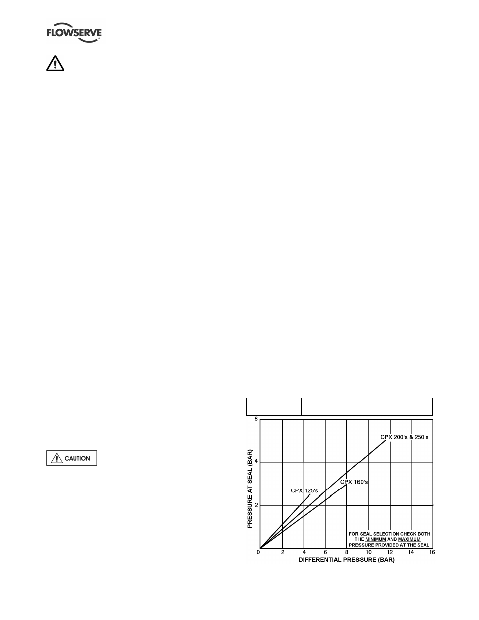
Double seals require a barrier liquid between the
seals, compatible with the pumped liquid.
With back-to-back double seals, the barrier liquid
should be at a minimum pressure of 1 bar (14.5 psi)
above the maximum pressure on the pump side of
the inner seal. (See chart.) The barrier liquid
pressure must not exceed limitations of the seal on
the atmospheric side. For toxic service the barrier
liquid supply and discharge must be in a safe area.
Special seals may require modification to auxiliary
piping described above. Consult Flowserve if unsure
of correct method or arrangement.
For pumping hot liquids, to avoid seal damage, it is
recommended that any external flush/cooling supply
be continued after stopping the pump.
Seal chamber pressure v generated head:
Mechanical seal
Use seal manufacturer's limits or ask seal
manufacturer to verify seal pressure