11 sealing arrangements – Flowserve CPXPM User Manual
Page 21
CPXPM USER INSTRUCTIONS ENGLISH 71569160 09-09
Page 21 of 28
flowserve.com
b) Refer to seal manufacturer's instructions to position
the mechanical seal rotating elements. The short
outboard seal is easier to assemble with a special
tapered tool fitted to the end of the shaft.
c) When the seals are in position, fit the seal cover
and tighten all fasteners.
d) Whilst supporting the seal housing, locate the
stubshaft on the adjustment stud to ensure
engagement. (Large pump sizes have a tapped
hole for fitting a lifting eye to assist with this
procedure.)
e) Rotate the impeller until the back clearance is
approximately 1 mm (0.04 in.).
f) Long studs may be used initially to locate the
seal housing and support the weight whilst the
impeller is rotated.
g) Ensure all flush connections are reconnected.
h) Refer to section 6.7, Setting impeller clearance for
setting dimensions and coupling fitting instructions.
i)
Fit the casing gasket and pump casing and
tighten all casing fasteners.
j)
Check that the shaft can turn freely without binding.
6.10.5 Impeller assembly and setting - cartridge
seal
a) Loosely fit the cartridge seal to the seal housing,
then fit and tighten onto the bracket.
b) Apply anti-seizing compound to the adjustment
stud.
c) Insert the impeller shaft and screw on until the
gap between the impeller and seal housing is
approximately 1 mm (0.04 in.).
d) Fit the casing gasket and pump casing and
tighten all casing fasteners.
e) Refer to section 6.7, Setting impeller clearance for
setting dimensions and coupling fitting instructions.
f) To set, or reset, a cartridge seal having a PTFE
setting ring-throttle and no separate setting clips,
finger tighten the seal cover studs nuts, then fully
torque up the sleeve screws.
g) Torque up the seal cover studs nuts.
6.11 Sealing arrangements
The following section shows details of the seal
arrangements. The dimensions provided are for non-
step balanced mechanical seals conforming to
EN 12757 L1K and L1N. Contact your nearest
Flowserve sales office or service centre if you require
further information, such as a mechanical seal
dimensional drawing, or are unsure of the specific
arrangement supplied. Refer also to section 4.5.5,
Auxiliary piping.
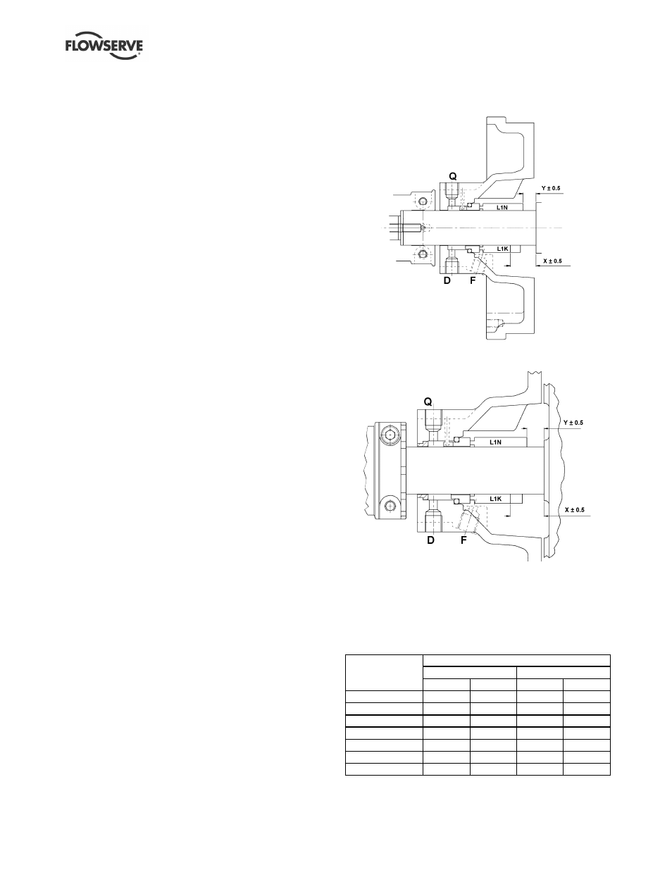
6.11.1 Single seal types
6.11.1a Single seal
Q - Rp ¼ in. quench
D - Rp ¼ in. drain
F - Rp ¼ in. flush
6.11.1b Single seal with external neck bush
Q - Rp ¼ in. quench
D - Rp ¼ in. drain
F - Rp ¼ in. flush
6.11.1c Single seal variants
1) Self setting collar.
2) Separate seal drive collar set to dimension 'X'.
3) Integral seal drive collar with screws set to
dimension 'X'.
L1K and L1N are seal lengths defined within seal
standard EN 12757.
Setting dimension (mm)
Stubshaft Ø 35
Stubshaft Ø 45
Pump size
X
Y
X
Y
125
25.5
13
-
-
160
25.5
13
36
21
65-160
25.5
13
36
21
100-160
25.5
13
36
21
200
25.5
13
36
21
250
-
-
36
21
315
-
-
36
21