3 general arrangement drawing – Flowserve LN User Manual
Page 29
LN, LNE, LNH, LNV, LNEV, LNC and LNEC USER INSTRUCTIONS ENGLISH 71576423 11-09
Page 29 of 32
flowserve.com
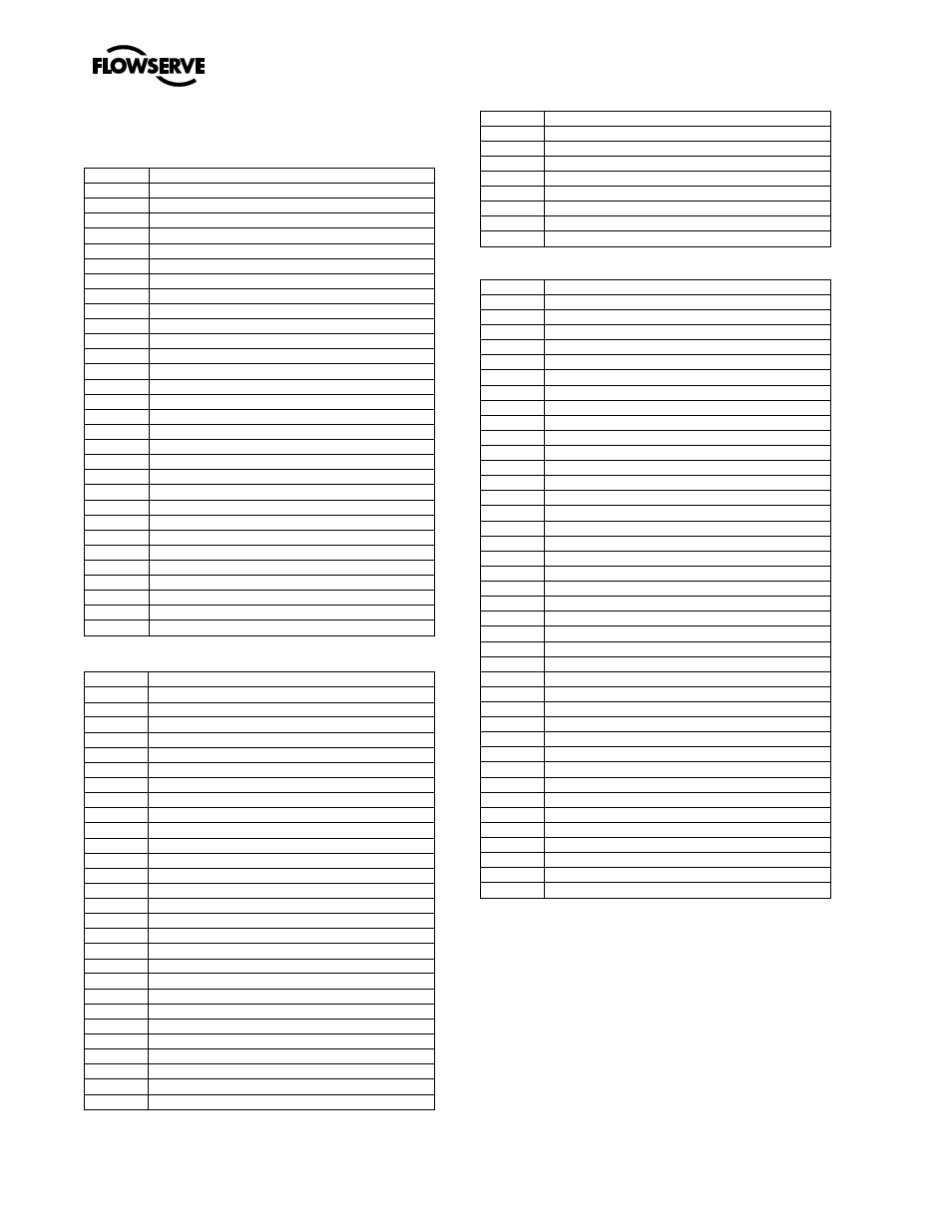
8.2 Sectional drawing parts list
8.2.1 LN, LNE and LNH
Ref no.
Description
1
Nameplate for bearing housing
2
Far side bearing housing
3
Far side bearing locknut
4
Far side bearing lockwasher
5
Far side ball bearing
6
Far side bearing housing cover
7
Mechanical seal assembly
8
Seal cover/gland stud with nut
9
Pump shaft
10
Pump shaft sleeve
11
Casing renewable ring
12
Top half casing
13
Impeller
14
Impeller key
15
Impeller hub ring
16
Screw for hub ring
17
Pipe for product recirculation
18
Bottom half casing
19
O-ring for shaft sleeve
20
Shaft sleeve nut
21
Water thrower
22
Drive side bearing housing cover
23
Drive side ball bearing
24
Drive side bearing housing
25
Coupling key
26
Locating pin for casing renewable ring
27
Grease nipple
28
Lantern ring
29
Gland packing
30
Gland
8.2.2 LNC and LNEC
Ref no.
Description
101
Casing lower
101.2
Gland stud
102
Casing upper
109
Casing gasket
161
Casing wear ring
161.1
Retaining pin
211
Bearing housing (DE)
211.1
Set screw
212
Bearing housing (NDE)
231
Ball bearing (NDE)
241
Ball bearing (DE)
251
End cover
251.1
Set screw
252
Bearing cover (DE)
252.1
Set screw
253
Bearing cover (NDE)
281
End cover gasket
301
Shaft
302
Key, impeller
309
Key, coupling
311
Impeller
321
Impeller hub ring
321.1
Set screw
351
Shaft sleeve
363
Sleeve nut
363.1
Set screw
364
Bearing locknut
366
Shim pack
366.1
Circlip
375
O-ring
378
V-ring
379
Lip seal
382
Distance sleeve
404
Gland packing
405
Lantern ring
406
Gland
500
Plan ll seal pipe
8.2.3 LNNV and LNNEV
Ref no.
Description
101
Casing lower
102
Casing upper
109
Casing gasket
161
Casing wear ring
161.1
Retaining pin
211
Bearing housing (DE)
211.1
Set screw
221
Bearing housing, lower
221.1
O-ring
241
Angular contact bearing
241.1
Bearing shim pack
248
Lower sleeve bearing
251
End cover
251.1
Stud
251.2
Nut
252
Bearing cover (DE)
280
Grease nipple
281
End cover gasket
301
Shaft
302
Key, impeller
306
Key, lower sleeve
309
Key, coupling
311
Impeller
321
Impeller hub ring
321.1
Set screw
351
Shaft sleeve
352
Lower sleeve
353
Bearing sleeve
363
Sleeve nut
363.1
Set screw
364
Bearing locknut
371
End cap
371.1
Capscrew
375
O-ring
378
V-ring
379
V ring
382
Distance sleeve
420
Mechanical seal assembly
500
Plan ll seal pipe
500.1
Product lube pipe
8.3 General arrangement drawing
The typical general arrangement drawing and any
specific drawings required by the contract will be sent to
the Purchaser separately unless the contract specifically
calls for these to be included into the User Instructions.
If required, copies of other drawings sent separately to
the Purchaser should be obtained from the Purchaser
and retained with these User Instructions.