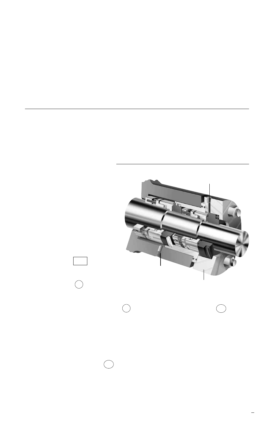
2 tandem seal installation, Typical tandem dura seal figure 2 – Flowserve Tandem Seal User Manual
Page 3
3
1.7 Check gland pilot and bolt holes to ensure they are adaptable to the
equipment and are the same as shown on the assembly drawing.
1.8 Handle all seal parts with care, they are manufactured to precise tolerances.
The seal faces; Part No. 3, Seal Ring, and Part No. 2, Insert, are of special
importance. These two sealing faces are lapped flat to three light bands (34.8
millionths of an inch). Keep the seal faces perfectly clean at all times.
2 Tandem Seal Installation
2.1 All Tandem Seal types are a combination of two single seals. See Fig. 2.
Various combinations of seal types may be used to comprise a Flowserve
Tandem. Other variations may include change in shaft packing materials
and the type of mounting for the stationary inserts.
2.2 Scribe a mark A on the
shaft or shaft sleeve
exactly flush with the
face of the seal chamber.
This will be the “reference
mark” for setting the seal
to the seal assembly
drawing. See Fig. 1.
2.3 Refer to the assembly
drawing provided with
the seal for collar
dimension settings
shown in a box .
Scribe marks B and C to
locate the inner edge of the
drive collars 5 for the outer
and inner seals. See Fig. 1.
2.4 Carefully place the gland ring 1 and the outer stationary insert 2A over
the shaft. Do not bump carbon parts against the shaft as they may chip,
crack or break.
Note: If the rotary units and shaft packings for the inner and outer seals are to
be assembled on a shaft sleeve, proceed as follows:
2.5 Place the insert holder IH over the shaft and into its proper position in the
gland ring as shown on the seal assembly drawing.
2.6. Lubricate the sleeve lightly with silicone lubricant before installing any of the
rotary unit parts.
External Sealing Liquid Inlet
Typical Tandem Dura Seal Figure 2
External Sealing Liquid Outlet
Bypass Flush