Description, 1 equipment check, Seal chamber requirements – Flowserve X-200 User Manual
Page 2
2
Congratulations
You have just purchased a reliable, long-life product manufactured by
the leading manufacturer of sealing systems in the world. With proper
installation and operation, this X-200 seal can be a valuable contributor
to your operation by significantly reducing the mean time between
planned maintenance (MTBPM) of your rotary equipment.
Description
This X-200 seal is a cartridge mounted end face welded metal bellows
mechanical seal, designed for ease of installation. No seal setting
dimensions are required. Removable setting devices provide proper
alignment. The welded metal bellows eliminates shaft fretting and resists
clogging or hang-up. Installation according to the following steps will
assure long trouble free life of the X-200 seal.
1 Equipment Check
1.1 Follow plant safety regulations prior to equipment disassembly:
• Lock out motor and valves.
• Wear designated personal safety equipment.
• Relieve any pressure in the system.
• Consult plant MSDS files for hazardous material regulations.
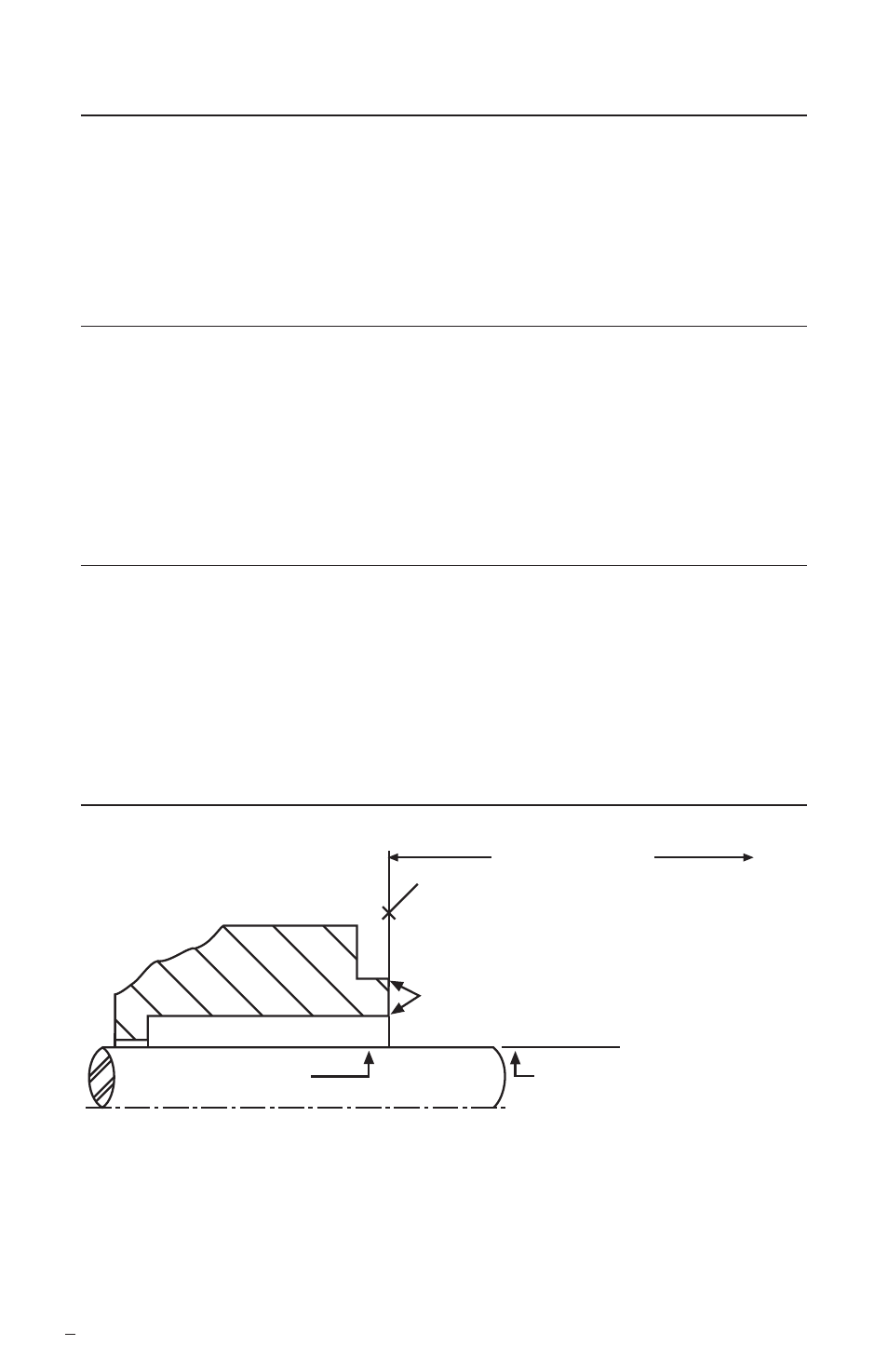
Seal Chamber Requirements
Figure 1
To first obstruction
Face of seal housing to be square to the
axis of the shaft to within 0.0005 mm/mm
(0.0005 inch/inch) of seal chamber bore TIR
and have a 1.6
μ
m (63
μ
inch) R finish or better
a
Gland pilot can be at either of these
register locations, concentric to within
0.125 mm (0.005 inch) of shaft or
sleeve OD TIR
Seal housing bore to have 3.2 μm
(125 μinch) R finish or better
Sleeve or shaft finish to be
0.8 μm (32 μinch) R or better
a
a
• Bearings must be in good condition
• Maximum lateral or axial movement of shaft (end play) = 0.25 mm (0.010 inch) TIR
• Maximum shaft runout at face of seal housing = 0.05 mm (0.002 inch) TIR
• Maximum dynamic shaft deflection at seal housing = 0.05 mm (0.002 inch) TIR
Shaft or sleeve OD
+0.000 mm (+0.000 inch)
-0.050 mm (-0.002 inch)
+0.000 mm (+0.000 inch) API 610/682
-0.025 mm (-0.001 inch) DIN/ISO
ANSI
The images of parts shown in these instructions may differ visually from the actual
parts due to manufacturing processes that do not affect the part function or quality.