2 x-200 seal installation – Flowserve X-200 User Manual
Page 4
1.2 Disassemble equipment in accordance with equipment
manufacturer’s instructions to allow access to seal installation area.
1.3 Remove existing mechanical seal and gland or compression
packing and packing gland (follower flange).
1.4 Make sure the shaft or sleeve is free of burrs, cuts, dents,
or corrosion that might cause leakage past the sleeve gasket,
as shown on the assembly drawing. Replace worn shaft or
sleeve. Remove sharp edges from keyways and threads.
1.5 Make sure the seal housing face is clean and free of burrs, cuts,
dents, or corrosion that might cause leakage the gland gasket or
misalign the seal gland.
1.6 Check equipment dimensions to ensure that they are within
the dimensions shown in Figures 1 and 2. Critical dimensions
include shaft or sleeve OD (A), a chamber depth (C), minimum
and maximum seal housing bore (B), and the minimum distance
to the first obstruction, (E) plus 0.125 inch.
1.7 Check gland bolting to ensure that bolt diameter (G) and bolt
circle (H) conform to the dimensions shown in Figure 2.
1.8 Handle the X-200 seal with care, it is manufactured to precise
tolerances. The sealing faces of the rotating face and stationary
face are of special importance. They are lapped flat to within
three light bands (34.8 millionths of an inch). Keep the seal
faces perfectly clean at all times.
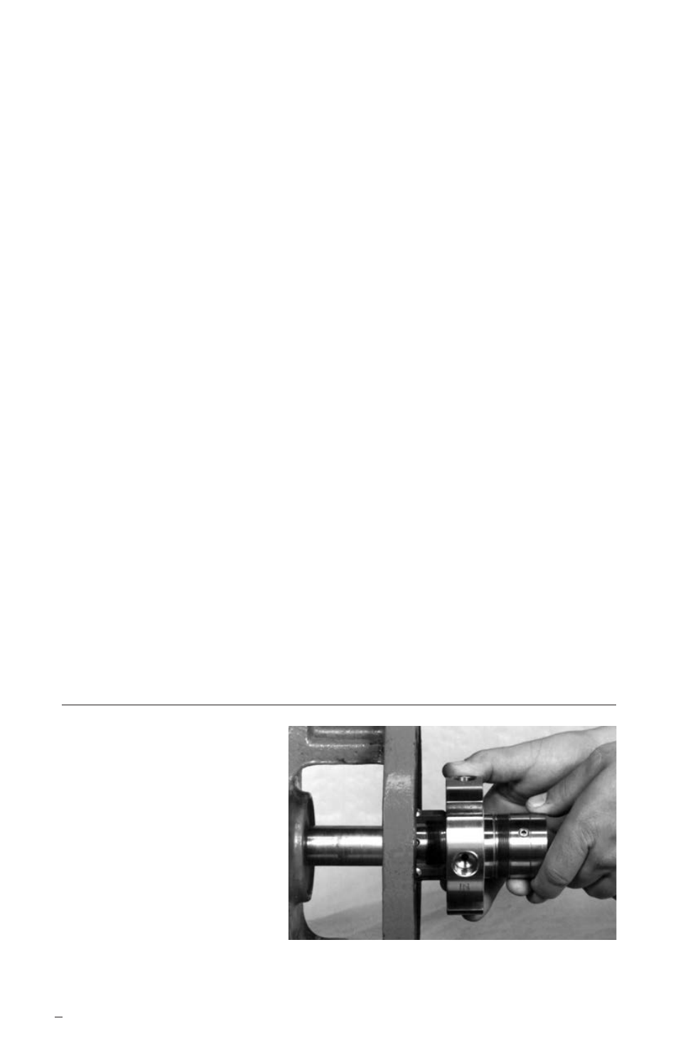
2 X-200 Seal Installation
4
Install X-200 Seal Cartridge
Figure 3
Tools needed:
• Open end wrench
for gland nuts
• Allen wrenches
provided
• Silicone lubricant
provided