Figure 2 – Flowserve GCX Series User Manual
Page 4
4
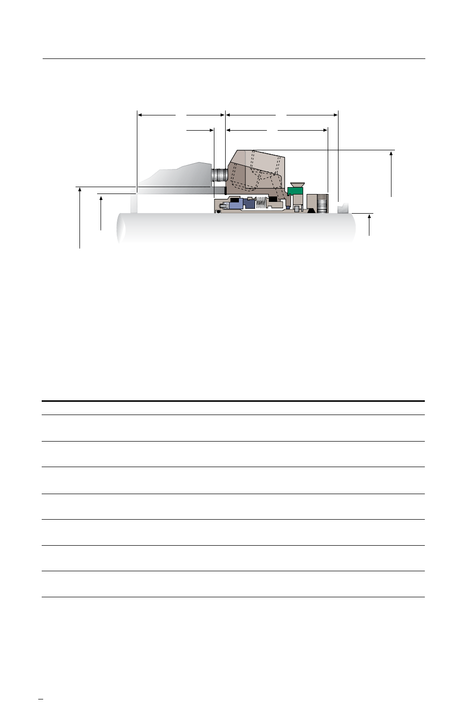
GCX Dimensional Data in millimeters (inches) - Standard Bore
Figure 2
G
K
J
Ø E
Ø A
Shaft Size
& Seal Size
Ø C
Ø D
F
A
C
D
E
F
G
J
K
L
M
Shaft &
Box Bore
Gasket
Gland
Sleeve Box Depth Outboard Dist. to Obst Bolt
Bolt
Seal Size Min Max
OD
OD
Penetration
Min Seal Length
Min Circle Slot Dia.
(1.125)
N/A
N/A
N/A
N/A
N/A
N/A
N/A
N/A
N/A
33, 35
N/A
N/A
N/A
N/A
N/A
N/A
N/A
N/A
N/A
(1.375)
N/A
N/A
N/A
N/A
N/A
N/A
N/A
N/A
N/A
44.45
63.5 73.0
80.0
25.5 - 127.0
6.5
8.1
64.3
66.5
98.4
14.3
(1.750) (2.500 2.875) (3.15) (4.94 - 5.00) (0.256)
(0.318)
(2.530)
(2.620)
(3.875 (0.562)
45, 48
66.7 73.0
80.0
125.5 - 127.0
6.5
8.1
64.1
65.5
98.4
14.3
(1.875) (2.625 2.875) (3.15) (4.94 - 5.00) (0.256)
(0.318)
(2.522)
(2.580)
(3.875) (0.562)
53
73.0 82.6
89.9
150.9 - 152.4
7.0
8.6
64.3
65.8
112.8
19.1
(2.125) (2.875 3.250) (3.54) (5.94 - 6.00) (0.275)
(0.337)
(2.530)
(2.590)
(4.440) (0.750)
86.1 95.3
101.2 160.5 - 162.0
7.9
9.4
64.1
66.8
123.8
19.1
(2.375) (3.388 3.750) (3.985) (6.32 - 6.38) (0.310)
(0.372)
(2.522)
(2.630)
(4.875) (0.750)
Goulds
91.1 92.1
100.1 160.5 - 162.0
16.5
19.2
64.0
66.3
123.8
19.1
(2.500-) (3.587 3.625) (3.942) (6.32 - 6.38) (0.651)
(0.755)
(2.521)
(2.609)
(4.875) (0.750)
IDP
85.7 95.2
100.1 179.3 - 180.8
4.0
5.6
76.6
79.7
155.6
14.2
(2.500-) (3.375 3.750) (3.942) (7.06 - 7.12) (0.158)
(0.220)
(3.014)
(3.139)
(6.125) (0.560)
65
92.1 109.5
117.2 182.6 - 184.2
6.7
8.3
90.1
93.3
142.9
22.2
(2.625) (3.625 4.312) (4.615) (7.19 - 7.25) (0.264)
(0.326)
(3.547)
(3.672)
(5.625) (0.875)
N/A - The GCX seal is not available in this size configuration
The images of parts shown in these instructions may differ visually from the actual
parts due to manufacturing processes that do not affect the part function or quality.