2 seal gard ii installation (see figure 2), Seal gard ii figure 2 – Flowserve Seal Gard User Manual
Page 4
4
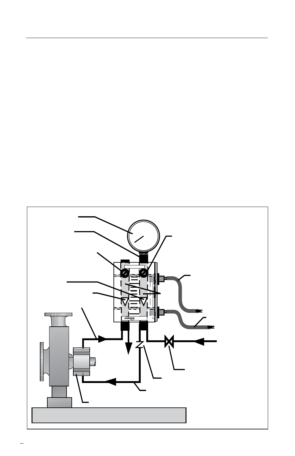
2 Seal Gard II Installation (See Figure 2)
2.1 Follow steps 1.1 through 1.4 above.
2.2 Pipe the seal flush liquid from the female 1/4 inch NPT fitting of the
check valve fitted to the TO SEAL tap on the bottom back of the Seal Gard
to the flush tap of the seal chamber. (In the case of packing, pipe to
the bottom lantern ring tap of the stuffing box housing).
2.3 Pipe the seal flush liquid from the top flush tap of the seal gland to
the female 1/4 inch NPT fitting on the Seal Gard marked FROM SEAL
tap on the bottom front of the Seal Gard. (In the case of packing, pipe from
the top lantern ring tap of the stuffing box housing).
2.4 Pipe the seal flush liquid from the female 1/4 inch NPT fitting marked
DISCHARGE on the bottom back of the Seal Gard to a seal water recovery
system.
Seal Gard II
Figure 2
100
PSI/kPa
50
Clean
Supply
Dual Flowserve Seal (ISC, SL-5200, etc.)
Discharge
to recycle
4
10
20
Seal Gard
™
II
GPH
H
2
O
LPH
H
2
O
On/off supply valve
Pressure gauge
Clean-out port
Return from seal line
Return From Seal control
valve
• Normally adjust Flow
From Seal here
• Close when inner seal fails
To gland or seal chamber inlet tap
High supply
alarm probe
option
Low supply
alarm probe
option
Check valve
Supply flow control valve
• Valve normally open 1/8 turn
from Return From Seal
control flow
• Adjust to control dilution if
inner seal fails
Return From Seal float
Supply float
Flow
tubes
Flow Solutions Division