Flowserve NT3000 Series User Manual
Page 15
15
NT 3000 Series Electro-Pneumatic Transducer Module FCD VLAIM0047-00 - 09/04
flowserve.com
Standard Explosion Proof EMI / RFI
Wiring Installation Procedures
(using conduit)
The NT 3000 transducer has been tested by an independent testing
laboratory to comply with the following industry standards:
EN 61000-4-2 Electromagnetic Compatibility (EMC) Part 4: Testing
and measurement techniques, Section 2 Electrostatic Discharge
immunity test, 1995.
EN 61000-4-3 Electromagnetic Compatibility (EMC) Part 4: Testing
and measurement techniques, Section 3 Radiated, radio frequency,
electromagnetic field immunity test, 1995.
EN 61000-4-4 Electromagnetic Compatibility (EMC) Part 4: Testing
and measurement techniques, Section 4 Electrical fast transient/burst
immunity test, 1995.
EN 61000-4-5 Electromagnetic Compatibility (EMC) Part 4: Testing
and measurement techniques, Section 5 Surge immunity test, 1995.
EN 61000-4-6 Electromagnetic Compatibility (EMC) Part 4: Testing
and measurement techniques, Section 6 Immunity to conducted
disturbances, induced by radio frequency fields immunity test.
The NT 3000 transducer complies with these standards when installed
following the minimum wiring procedures.
The housing must be grounded. Normally the housing is grounded
through the valve to the local superstructure. When the positioner is
grounded, the on-board filtering will be effective. Therefore, a green
internal ground screw is provided. The ground wire should be as short
as possible.
Proper NT 3000 field wiring includes three elements: conductive
conduit (armor), drain wire, and shielded wire.
Conductive Conduit The conduit can be rigid or flexible and must
be conductive. The conduit provides additional protection in the event
the shield contains an opening and is required to be within six feet of
the NT 3000 transducer and within six feet of any radios or microwave
sources. The conduit system includes an aluminum fitting at the NT
3000 transducer.
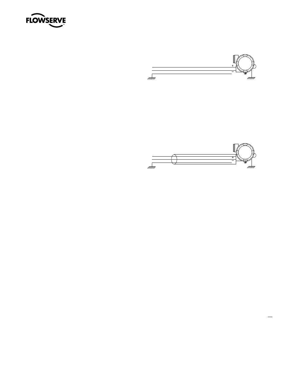
Figure 9 – NT 3000 Transducer, Drain Wire
�������
�����
��
����
Drain wire The drain looks like a bare ground wire and is not a
shield. The drain wire is provided by the cable manufacturer and
provides a path to ground for any noise, or can be a path for ground
loops. Therefore, the drain should be terminated only at one end of the
loop (normally the source). The drain extends from the source to the
NT 3000.
Figure 10 – NT 3000 Transducer, Shielded Wire
�������
�����
������
��
����
Shielded Wire This is standard insulated instrumentation wire with
a conductive aluminum foil wrapped around the conductors. The
shield provides a protective metal barrier to keep out electrical noise.
Shield weak points are found at the beginning, end and other openings.
Sometimes the foil wrap is outside of the cable manufacturer’s speci-
fication for overlap. Any openings in the shield (i.e. bends with under
tolerance overlap) provide a path for electrical noise to infect the current
signal. The shield extends from the source to the NT 3000 transducer.
Grounding of the shield should be at one end only (the same end as the
drain wire).
NOTE: Cable tray or ladder will not provide protection from electrical
noise.
This procedure will protect against noise generated close to the NT
3000 transducer. However, generating electrical noise at the source
power supply (DCS, etc.) is possible and can be due to ground loops in
the source power supply or other contamination. Any noise generated
at the source can affect the NT 3000 transducer.