Flowserve Valtek Position Pac User Manual
Page 5
29-5
Flowserve Corporation, Valtek Control Products, Tel. USA 801 489 8611
Position Transmitter
1. Remove the housing cover from the Position Pac.
WARNING: On explosion-proof installations,
disconnect electrical power or be certain the
area is safe from combustible atmospheres be-
fore removing the housing cover.
2. Wire the Position Pac transmitter in series with a
12.5-40 VDC power supply and a milliamp meter.
NOTE: Instructions within parenthesis ( ) refer to
older Position Pac models characterized by a white
label.
CAUTION: Do not apply a voltage greater than 40
volts to transmitter terminals or the circuit will be
damaged.
3. Be certain the CW/CCW Switch located next to the
potentiometer (Direct/Reverse Switch located next
to the wire terminal block) is set to provide the de-
sired output signal action. In the CW (DIR) position,
a clockwise rotation of the Position Pac shaft will
cause the output signal to increase. In the CCW
(REV) position, a counterclockwise stem rotation
causes the signal to increase.
4. Stroke the valve to the closed position.
WARNING: Keep hands, hair, clothing, etc. away
from moving parts when operating the valve.
Failure to do so can cause serious injury.
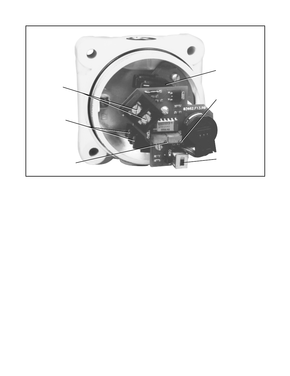
5. Referring to Figure 5, adjust the ZERO adjusting
screw with a small, straight end screw driver, until the
meter reads 4 mA DC.
6. Stroke the valve to the open position.
7. Adjust the SPAN adjusting screw until the meter
reads 20 mA DC.
8. Stroke valve to the closed position and recheck the
meter for 4 mA DC. Some readjusting of the calibra-
tion may be required. Repeat steps 4-8 until satis-
fied.
9. If calibration is unsuccessful after following this pro-
cedure, one of two problems may exist: (a) The ori-
entation of the Position Pac stem may need to be
adjusted. (b) The ZERO and SPAN potentiometers
may be adjusted out of range.
NOTE: The electrical travel of the potentiometer is
340 (150) degrees. To operate properly, the poten-
tiometer wiper must stay within the center 185 de-
grees of its 340 degree electrical range during the full
stroke of the valve.
9a. To adjust, stroke the valve to its middle position.
Loosen the potentiometer collar nut. While measur-
ing the voltage between pins 1 and 2 on the back of
the potentiometer, rotate the potentiometer until the
voltage is between 0.55 and 0.65 volts. Retighten
the potentiometer being careful to keep the potenti-
ometer oriented in the same position.
Transmitter zero
Adjusting Screw
(pot)
Limit switch
adjustment cams
(not shown)
Transmitter span
adjusting screw
(pot)
Clockwise/counter-
clockwise switch
Transmitter
terms
block
Limit switch
wiring terminal
Figure 5: Calibration Points