Figure 2: body assembly, Removing actuator from body, Disassembling the body – Flowserve Valtek Valdisk Control Valves User Manual
Page 4
10-4
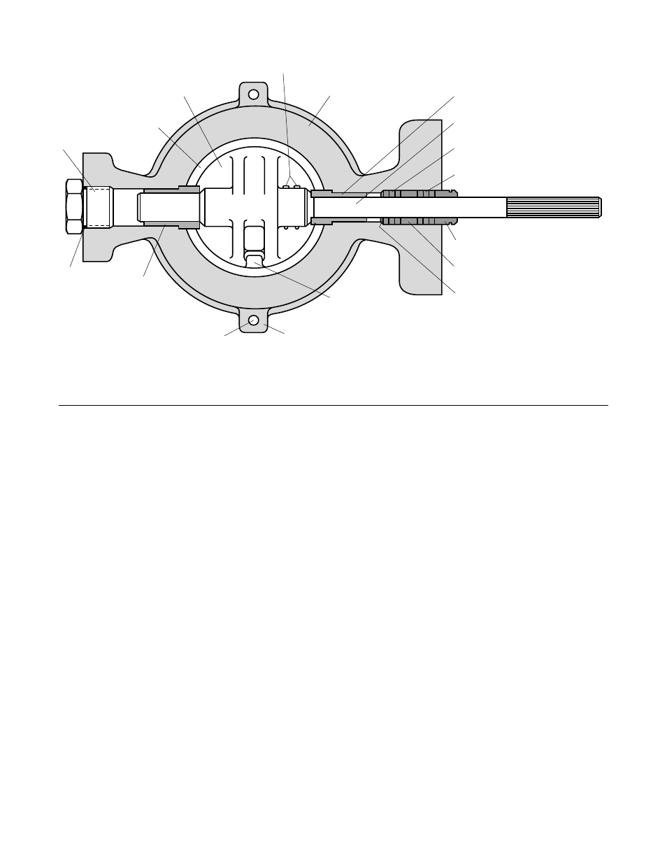
Figure 2: Body Assembly
NOTE: Item numbers correspond directly to the valve's bill of material. Refer to it for specific part numbers.
Body
(Item No. 1)
Taper Pins
(Item No. 52)
Shaft Bearing
(Item No. 83)
Shaft
(Item No. 51)
Inner Packing
(Item No. 88)
Outer Packing
(Item No. 88)
Packing Follower
(Item No. 87)
Packing Spacer(s)
(Item No. 93 - 95)
Packing Retainer
(Item No. 85)
Seat Retainer Clip
(Item No. 123)
Shaft
Plug
(Item No. 122)
Disc
(Item No. 50)
O-ring
(Item No. 61)
Seat
Shaft
Bearing
(Item No. 83)
Disc Stop
Seat Retainer Bolt
(Item No. 124)
5. After the valve is completely removed from the line, slowly
relieve air pressure from the actuator.
Removing Actuator From Body
In most cases, both the body assembly and the actuator are
easier to disassemble with the actuator removed from the
body. To do so, proceed as follows:
1. Support actuator assembly by the lifting ring before dis-
connecting it from the body assembly.
2. Remove the transfer case cover bolts. Carefully pry or
slide the cover plate from the end of the shaft.
3. On Valtek actuators with a clamping lever arm design,
loosen the linkage bolt.
4. Loosen the actuator adjusting screw to release spring
pressure.
5. Remove the bolts connecting yoke to the actuator subas-
sembly.
6. Slide entire actuator assembly off the shaft. For Valtek
actuators with a clamping lever-arm design, it may be
necessary to wedge the halves of splined lever arm apart
to loosen it from the shaft splines.
Disassembling the Body
To disassemble the body, refer to Figures 1, 2 and 5 and
proceed as follows:
1. On Valdisk valves supplied with seat retainer screws,
remove the seat retainer screws and retainer clips. Lift
the seat retainer out of the valve body. (Refer to Figures
1A, B, C).
2. On valves supplied with retainer snap-ring configuration,
carefully insert a screwdriver in the key slot provided in
the retainer; pry the retainer and snap ring out of the valve
body. (Refer to Figure 1D).
3. Remove the gland flange by removing both packing nuts.
It is not necessary to remove the studs.
4. Drive the taper pins out of the disc by tapping on the small
end of the pins using a punch and hammer.
5. Remove the end plug (optional bolted flange and seal if
applicable).
6. Remove shaft by inserting a press or a nylon rod (or simi-
lar material) into bodyís blind end, and using a hammer,
carefully tap the shaft through the body.
CAUTION: Take special care not to damage the splined
end of the shaft during disassembly.
To prevent scratching the sealing surface of the disc while
removing the shaft, place supports underneath the disc.
This also prevents the shaft from binding in the body as
the shaft comes off the bearing surfaces.