Valve disassembly – Flowserve Valtek Mark One and Mark Two Control Valves User Manual
Page 9
9
®
Valtek Mark One and Mark Two Control Valves FCD VLENIM001-01-AQ - 8/14
5.12.
Spray a soap solution around the actuator cylinder retaining
ring and actuator stem guide to check for air leaks through
the O-rings.
5.13.
Clean any dirt and other foreign material from the plug stem.
5.14.
If an air filter is supplied, check and replace cartridge if nec-
essary. Drain any moisture accumulated in the air filter.
6. Valve Disassembly
6.1.
To disassemble the valve body, refer to Figures 1, 2 and 3
then proceed as follows:
WARNING: Depressurize line to atmospheric pressure and
drain all fluids before working on the valve. Failure to do so
can cause serious injury.
6.2.
If valve is air-to-open, apply air under the piston to lift the
plug off the seat before taking the valve apart. If valve is air-
to-close, proceed to step 6.3.
6.3.
Remove the bonnet flange bolting and lift actuator, bonnet
and plug out of the valve. Once removed, the actuator, bon-
net and plug assembly (called the top works) should be low-
ered and blocked to prevent rolling during the disassembly
of the top works.
WARNING: Danger exists in removing the actuator, bonnet
and plug, especially if a pressure balanced plug is used. The
pressure balanced sleeve may stick to the plug and fall dur-
ing disassembly, causing possible serious injury and dam-
age to the valve or nearby equipment. If sleeve is observed
sticking to the plug, steps 6.3.1 to 6.3.4 should be consulted.
CAUTION: Heavy actuators may require a hoist. Lift the valve
with the yoke legs using a lifting strap and a hoist. Great care
should be taken to lift the actuator and plug straight out of
the body to avoid damage to the plug and seat.
6.3.1.
If the sleeve is observed sticking to the plug during removal,
fully extend the plug by applying air above the piston, allow-
ing the sleeve to remain in the body and the bonnet to rise
above the body.
6.3.2.
In the gap between the top of the sleeve and the bottom of
the bonnet, place wooden blocking of equal thickness in at
least three places. The wooden blocks must not extend in
far enough that they interfere with plug movement. The plug
must be allowed to stroke up to the bonnet.
6.3.3.
By applying air below the piston, retract the plug until the
plug head is freed from the sleeve. Once the plug is free from
the sleeve, remove the plug and bonnet assembly from the
body.
6.3.4.
Lift the pressure balanced sleeve out of the valve body using
lifting points on the top of the sleeve.
NOTE: In many small Mark One valves, the seat retainer and
pressure balancer sleeve are one and the same part. In larg-
er valves, there are separate pressure balancer sleeves and
seat retainers.
6.4.
Lift retainer, seat ring and gaskets free of the body. Care
must be taken not to damage the gasket surfaces in the body
when the gaskets are removed.
6.5.
Valves with soft seats (see figure 4) require the seat ring to
be inspected and possibly disassembled. Check to see that
seating surfaces on the plug and seat assemblies are free of
damage. If the seat insert is worn, remove it from the assem-
bly. Since the plug seating surface does not come in contact
with the seat insert retainer, it is not necessary to correct any
minor damage to that part. The plug seating surface can be
re-machined to a 30 degree angle. Lapping is not required
when proper reassembly procedures are followed.
6.6.
Loosen the stem clamp and unscrew the plug from the actu-
ator stem.
WARNING: Danger exists when working with large valves
and heavy parts. Take care to properly support large parts to
avoid damage to the parts of nearby equipment or personnel.
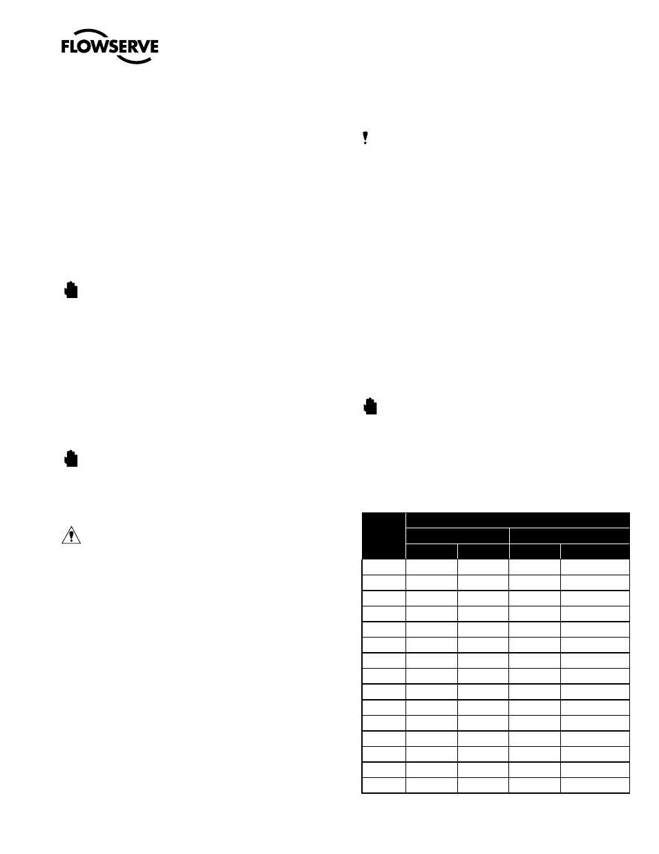
Bolt Size
(inches)
Bolt Size (inches) Bolt/Stud Material
Carbon Steel
Stainless Steel
ft-lbs
Nm
ft-lbs
Nm
5/8
80
108
50
68
3/4
140
190
90
122
7/8
230
312
150
203
1
350
475
220
298
1 1/8
510
691
330
447
1 1/4
730
990
460
624
1 3/8
990
1342
630
854
1 1/2
1320
1790
840
1139
1 5/8
1710
2318
1080
1464
1 3/4
2170
2942
1400
1898
1 7/8
2700
3661
1700
2305
2
3350
4542
2100
2847
2 1/4
4050
5491
2530
3430
2 1/2
4850
6576
3010
4081
3
7273
9861
5913
8017
* All values are ±10%
Table II: Suggested Bonnet Bolting Torque Values
STOP!
STOP!
STOP!