Flowserve 132000 LinedFlow Linear Lined Globe Control Valve IOM User Manual
Page 5
®
User Instructions LinedFlow - KMENIM3202-02 01/12
5
7
NORMaL OPERaTION aND MaINTENaNcE
These installation, operating and maintenance instructions
cannot contain all detailed information on all possible
versions for reasons of clarity and, in particular, cannot take
into consideration all imaginable cases for setup, operation
and maintenance. Therefore, only primarily instructions
are contained, which are required for the intended use in
industrial applications. If anything is not clear, particularly if
any detailed information on the specific product is missing,
clarify as required with the responsible FLOWSERVE repre-
sentative.
8
TROUBLESHOOTINg
When troubleshooting or during general maintenance,
always observe Section 1 “Safety precautions”.
DaNgER:
If a valve contaminated with dangerous sub-
stances has to be removed from the system or pipeline,
decontaminate it properly before performing further mainte-
nance work.
9
PODUcT DEScRIPTION
9.1 Housing
The body material is made of GGG40.3 (standard), other
body materials are also available from the manufacturer on
request. For valve bodies with plastic liners: See Table 2b
for coating materials.
The liner thickness is at least 5 mm for DN25 and higher
and 3.5 mm for DN15 and DN20.
10 BONNET
The bonnet is connected with a form fit to the valve body
providing, on the one hand, a potential compensation
between the housing and bonnet and on the other a defined
compression force for the body seal and bellows. The bon-
net is provided with a blowout safety system. This means
that the valve stem cannot be pulled or pressed upward out
of the bonnet.
11
PLUg aND SEaT
The seat and plug are screwed, i.e. replacement is possible
at any time when the Kvs value changes or for repair. The
plug is screwed to the bellows and secured against loose-
ning by a PTFE insert. For smaller Kvs values, a Hastelloy
insert can be provided in the plug as well as in the seat (see
Table 3).
The possible material combinations and available Kvs values
and curves are shown in Table 3.
12 BELLOWS
The bellows seal is manufactured from modified PTFE.
TF1620 for DN15, DN20 and DN25 and TFM1600 for sizes
DN40, DN50, DN80 and DN100. The bellows is designed
and tested on a standard basis for an operating pressure of
16 bars at 120 °C. The pressure/temperature limitations are
limited only by the lining material, not the bellows: Observe
the additional operating forces required by the bellows for
sizing your actuator.
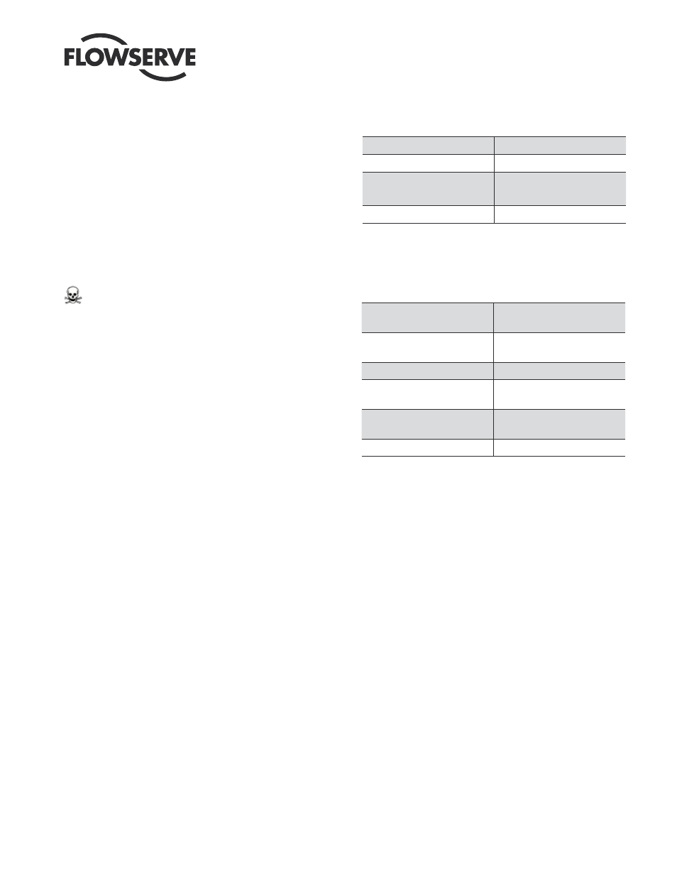
Table 2a: Body Specifications
Body material
0.7043 (GGG40.3)
Pressure class
PN16
End connections
(Flanged)
DIN PN 16
ANSI Class 150
Liner thickness
4 – 6 mm
Table 2b: Liner Materials
PFA
Perfluoralkoxypolymer
(Standard)
PFA conductive
Perfluoralkoxypolymer,
electrically conductive
PVDF
Polyvinilidenfuoride
ETFE
Ethylene Tetrafluorethylene–
Copolymer (Tefzel
®
)
FEP
Tetrafluorethylene
Perffluorpropylene
PP
Polypropylene