Mark 100 – Flowserve Valtek Mark 100 Control Valve User Manual
Page 9
Flow Control Division
Mark 100
FCD FCAIM0100-02
Mark 100 Installation, Operation and Maintenance Instructions
9
Metal Multi-Seals Install wave spring followed by four seal
rings. Stagger ring openings by at least 90 degrees. Take care
not to bend the seal rings as they are installed.
O-ring with Back-up Rings Both the O-ring and back-up rings
can stretch over plug and into place.
4. Lower the plug into the body and sleeve. Care should be taken
with the plug seals to avoid scoring or galling the sealing surface
while fitting them into the sleeve bore. With metal multi-seals
and carbon triple seals, use a ring compressor on the rings. A
suitably sized screw-type hose clamp will also serve to com-
press the rings for reassembly.
5. Lower the bonnet onto the plug and body, taking great care to
avoid scoring the plug stem.
6. Once the bonnet is resting squarely in the valve body, finger-
tighten the bonnet flange bolting.
7. Reinstall the packing and guides referring to the appropriate
packing installation manual and reinstalling new packing exactly
as shown. Make sure at least
1
⁄
8
" is left at the top of packing box
for the top guide to enter. Different spacer lengths permit a wide
variety of packing configurations, such as twin seal and vacuum-
pressure packing.
c
WARNING: Valves with extended bonnets must not have
lower packing installed. Instead, lower packing rings
should be installed with the upper set. Lower packing
installed in extended bonnets will diminish the integrity
of the packing assembly.
NOTE: Graphite guide liners should be replaced each time the
valve packing is replaced. Do not rebuild the valve without new
graphite liners in the guides.
8. Replace and tighten the packing gland and bolting. Refer to the
packing installation manual for specific details on maintaining
the style of packing supplied.
9. Turn actuator back onto the body assembly, without turning the
plug inside the bonnet. Leave a
3
⁄
32
" to
1
⁄
8
" (2 mm to 3 mm) gap
between the mating surfaces of the bonnet and yoke. Tighten
yoke bolting to close this gap. Firmly tighten the yoke bolting.
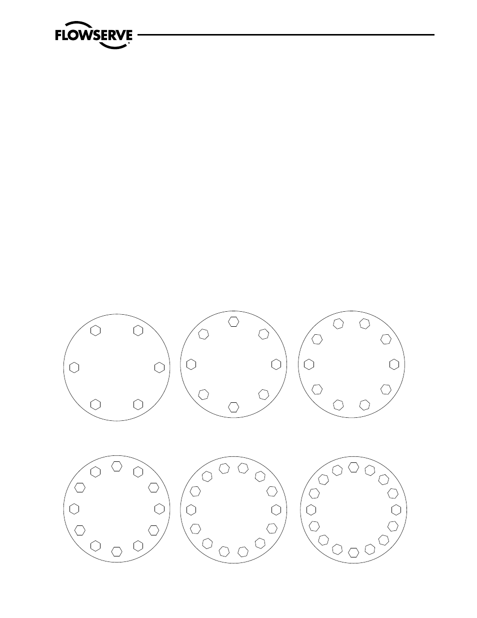
Figure 5: Bolt Patterns
1
2
3
4
5
6
1
2
3
4
5
6
7
8
1
2
3
4
5
6
7
8
9
10
11
12
1
2
3
4
5
6
7
8
9
10
11
12
13
14
1
2
3
4
5
6
7
8
9
10
11
12
13
14
15
16
Six Bolt Pattern
Eight Bolt Pattern
1
2
3
4
5
6
7
8
9
10
Ten Bolt Pattern
Twelve Bolt Pattern
Fourteen Bolt Pattern
Sixteen Bolt Pattern