Flowserve 191400 Series User Manual
Page 3
3
3
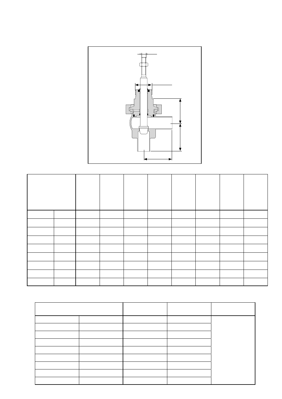
TECHNICAL DATA
Fig. 1
M 10
A
A
F
M 38 x 1,5
a ↑
Valve size
Dim. A
DIN 11850
Weld ends
Dim. A
ISO 2037
BS 4825
Part 1
Weld ends
Dim. A
DIN EN
ISO 1127/
DIN 2463
Reihe 1
Weld ends
Dim. A
DIN 11851
Screwed
ends
Dim. A
11864
Form
GS-A
Screwed
ends
Dim. A
DIN 32676
Clamp
ends
Dim. A
ISO 2852
Clamp
ends
Dim. A
ASME
BPE-97
DN 10 - 15
½"
60
60
60
80
78
77
-
80
DN 20
¾"
60
60
60
83
80
77
-
80
DN 25
1"
65
65
65
93
90
85
85-NS25
-
DN 32
1¼"
70
70
70
101
99
90
-
-
DN 40
1½"
75
75
75
107
105
95
95-NS38
-
DN 50
2
85
85
85
120
116
105
105-NS51
-
DN 65
2½"
100
100
100
140
136
128
120-NS63,5
-
DN 80
3"
110
110
110
155
152
138
128-NS76,1
-
DN 100
4"
120
120
120
173
169
148
140-NS101,6
-
Dimensions (mm) and weights (kg)
Valne size
Dimension F
191400
Dimension F
191700 und 800
Weight
without actuator
DN 10 - 15
½"
56
81
Upon request
DN 20
¾"
56
81
DN 25
1"
56
81
DN 32
1¼"
56
81
DN 40
1½"
63
82
DN 50
2
70
84
DN 65
2½"
77
105
DN 80
3"
90
109
DN 100
4"
100
115
b ⇒