Flowserve G4 Marathon Sleeveline Plug Valves User Manual
Page 11
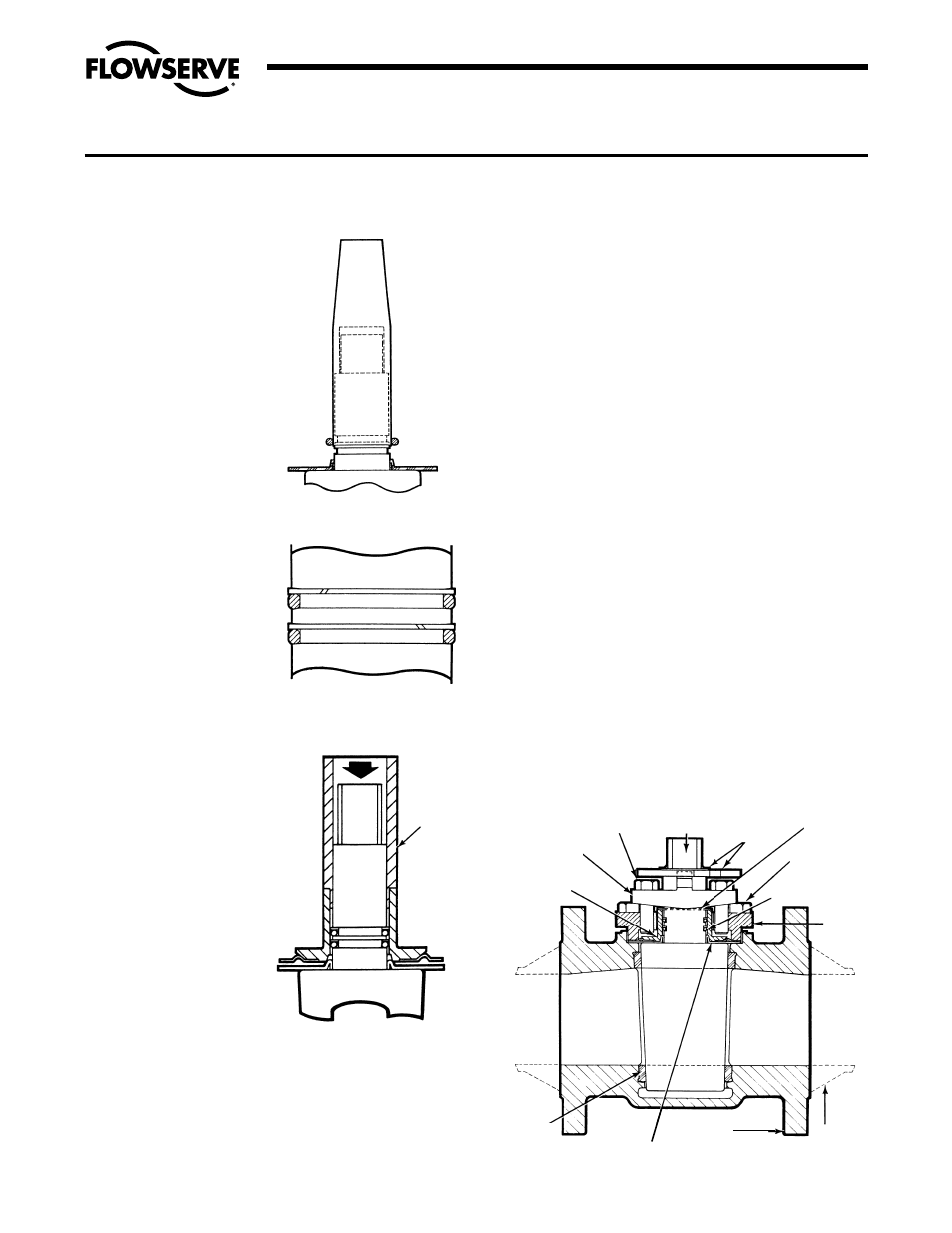
8. Using the diaphragm
guide to protect the
o-ring from the stem
edge, install the first
o-ring by “rolling” it with
your fingers over the
guide and into the lower
stem groove (Figure V
B-6). Install Teflon split
ring in a similar manner
such that it is located
above the o-ring inside
the lower groove. See
Figure V B-7.
9. Install second o-ring
and split ring in upper
groove in a similar
manner, except that the
diaphragm guide should
be raised by hand so
that the lower edge of
the guide does not
contact the lower o-ring
assembly. See Figure
V B-7. Coat both o-ring
assemblies liberally
with Krytox
®
grease.
Remove the guide.
10. Place the thrust
collar/diaphragm over
the plug stem and gently
maneuver it over the
o-rings onto the PFA
diaphragm. The thrust
collar is driven into
place through the use of
the thrust collar guide,
part series #BY86273A,
and an arbor press
(Figure V B-8).
11. Place the grounding
spring (Part 17) over
the plug stem.
12. Apply a thin, even coat
of silicone on the entire
surface of the 2° plug
taper.
13. Place the top cap and adjuster over the plug stem. Place
this subassembly into the valve body. Using an arbor or
hydraulic press, push down on the top cap evenly until
the top cap gasket pad seats firmly against the body
counterbore. Apply thread locking compound to the
threads of the top cap fasteners. Tighten the top cap
SECTION V
B. VALVE ASSEMBLY – 1"-8" G4 MARATHON, G4R MARATHON
Flow Control Division
Section 1.0
11
fasteners to the torque values found in Torque Table #1a
& #2b on page 12.
14. Remove the valve from the arbor press, loosen the
adjuster fasteners, and operate the plug several times. It
will turn hard at first but will then loosen and turn freely.
15. Tighten the adjuster fasteners (Part 12A) until a reason-
able turning torque (Ref. Table #2) is obtained. The 8"
and larger valves are placed in an oven at 200°F for a
minimum of six hours prior to final adjustment with the
plug in the open position. After removal from the oven
and valve has cooled, loosen the adjuster fasteners. Turn
the plug several times. Retighten the adjuster fasteners
until a reasonable plug turning torque is obtained. The
height of the plug port should be positioned approxi-
mately
1
/
16
" above to flush with the body port.
16. Place the stop collar (Part 19A) and retainer on the plug
stem. The stop collar should point in the direction of flow.
17. The valve is now ready for test and use.
18. LEAK TESTING: Anytime a valve has been modified in
any manner, including fastener changes, it should be
retested. Normal testing using gas, should be at 150 PSI
for Class 150 and 300 PSI for Class 300 valves from
1
/
2
" through 6". It should be noted, however, that this test
does not meet the requirements of ANSI, API or MSS.
For test procedures complying with these specifications,
refer to the appropriate published specification or
contact Flowserve.
FIGURE V B-6
FIGURE V B-7
FIGURE V B-8
THRUST
COLLAR
GUIDE
ADJUSTER
FASTENERS (12A)
PLUG (2)
ADJUSTER (12)
GROUND
SPRING (17)
THRUST
COLLAR
(11)
DIAPHRAGM (6)
STOP
COLLAR &
RETAINER
(19A)
TOP CAP
FASTENERS (3A)
TEFLON BACK-UP
RINGS (20) &
O-RINGS (21)
TOP
CAP (3)
BODY (1)
G4R
MARATHON
SLEEVE (5)
BODY,
G4 MARATHON
FIGURE V B-9
ASSEMBLED G4 MARATHON OR G4R MARATHON VALVE