G4 marathon, g4r marathon – Flowserve G4 Marathon Sleeveline Plug Valves User Manual
Page 8
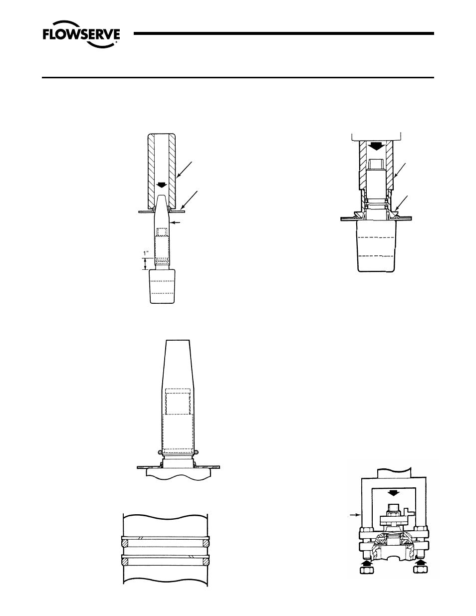
5. The plug stem and dia-
phragm guide are to be
checked for nicks or
burrs before installing
the diaphragm. Nicks
on these surfaces
could result in
scratches on the lip
of the diaphragm.
Assemble diaphragm
over plug stem with the
aid of the diaphragm
guide, part #BY86272B,
and assembly tool, part
#BY80019A (Figure
V A-5).
6. Using diaphragm guide
to protect the o-ring
from the stem edge,
install the first o-ring
by “rolling” it with your
fingers over the guide
and into the lower stem
groove (Figure V A-6).
Install Teflon split ring
in a similar manner
such that it is located
above the o-ring inside
the lower groove. See
Figure V A-7.
7. Install second o-ring
and split ring in the
upper groove in a
similar manner, except
that the diaphragm
guide should be raised
so that the lower edge
of the guide does not
contact the lower o-ring
assembly. See Figure
V A-7. Coat both o-ring
assemblies liberally
with Krytox
®
grease.
Remove the guide.
8. Place the thrust collar/
diaphragm over the
plug stem and gently
maneuver it over the
o-rings onto the PFA
diaphragm. With the
thrust collar guide, P/N
BY86273B, centering
the thrust collar assy;
force down (with arbor
press) the thrust collar
guide to seat the
thrust collar on the
diaphragm. See Figure
V A-8. Remove guide
from plug stem.
9. Place grounding spring
over plug stem sliding
it down to the thrust
collar.
10. Apply a thin, even film of silicone or customer approved
lubricant to the entire surface of the 2° plug taper.
11. Take plug (preassembled with diaphragm, thrust collar
and grounding spring) and place it into body. Using a
soft head mallet, tap top of plug slightly to seat plug into
sleeve taper. The plug at this time will be setting up
above the body counterbore approximately
1
/
4
". The
plug ports should be lined up in an open position.
12. Place the top cap assembly over plug and slide it down
until it rests on the thrust collar.
13. Assemble four fasteners thru top cap and body. With “U”
shaped push plate, part #BY86592A, resting on the top
cap (Figure V A-9), force the top cap down (with arbor
press or pneumatic clamping arrangement) to seat the
top cap against the valve body counterbore. While holding
the cap in this position, assemble nuts on underside of
body flange to a finger tight position against the flange.
NOTE: All fastening torques
are for corrosion free fasten-
ers and nuts. Precautions
must be taken not to exceed
recommended fastening
torques.
SECTION V
A. VALVE ASSEMBLY –
1
/
2
" &
3
/
4
" G4 MARATHON, G4R MARATHON
8
FIGURE V A-7
FIGURE V A-6
Flow Control Division
Section 1.0
FIGURE V A-5
ASSEMBLE DIAPHRAGM ON
PLUG
DIAPHRAGM
ASSEMBLY
TOOL
DIAPHRAGM
DIAPHRAGM
GUIDE
If damaged the
plug taper and 1"
in length of stem
must be repolished
to a surface finish
of 16AA on the
taper and on stem.
FIGURE V A-8
SEAT THRUST COLLAR ON
DIAPHRAGM
THRUST
COLLAR
GUIDE
THRUST
COLLAR
FIGURE V A-9
ASSEMBLE TOP CAP ASSEMBLY
OVER PLUG AND PUSH INTO
BODY. APPLY THREAD LOCKING
COMPOUND.
TOP CAP
ASSEMBLY
PUSH PLATE