Adjusting the minimum pressure cutoff feature, Calibrating i/p module zero and span settings, Flowserve – Flowserve APEX 8000 High-Performance Positioner User Manual
Page 8
Calibrating I/P Module Zero and Span Settings
NOTE: Although calibration can be accomplished using the output pressure gauge on the I/P module, its accuracy is ±3 percent. The standard
gauge should be removed only for calibration and more accurate calibration equipment of ±0.1 percent of span should be used. The pressure
gauge port is 1/8-inch NPT. Calibration manifolds are available from the factory (Part No. 97370).
1. Connect I/P module to a supply pressure between 30 to 150 psi.
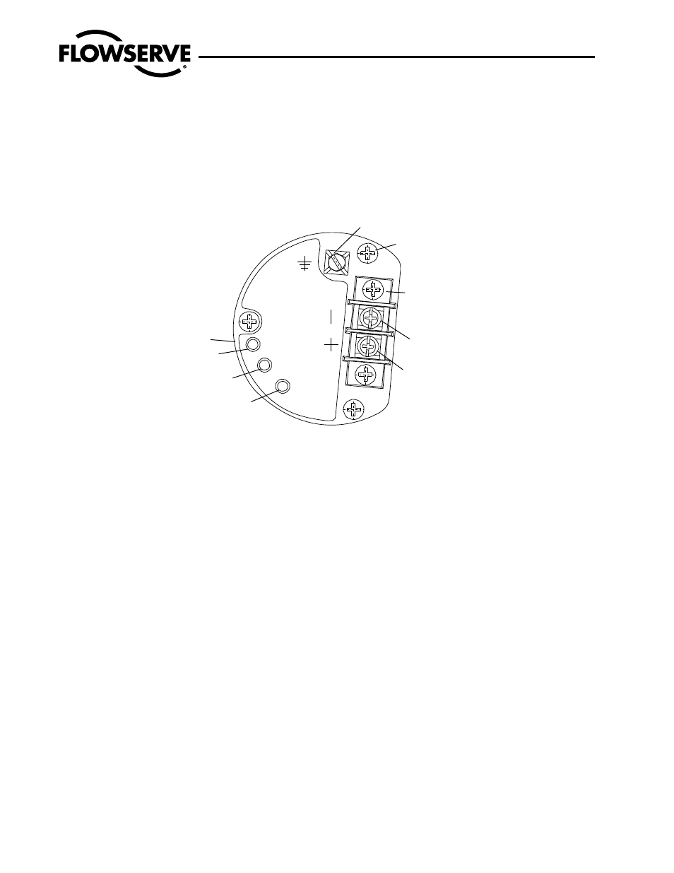
2. Remove I/P module housing cover. (See Figure 7.)
Figure 7: KM82 Circuit Board Module with Housing Cover Removed
WARNING: Be certain power to I/P module is disconnected before removing housing cover in explosive atmospheres; otherwise personal
injury may occur.
3. Before adjusting the zero and span, be certain the MPC fea ture is disabled. Refer to Step 7 in the ‘Adjusting the Minimum Pressure Cutoff
Feature’ section.
4. Connect a current source to the terminal block on circuit board.
NOTE: The zero and span adjustments are multi-turn potentiometers (pots) that have no stops on the ends of their travel; however, they
have a slip clutch to prevent damage from over-adjustment. The pots also make a clicking noise when they have reached adjustment
limits.
5. Apply a 4.0 mA signal to the input. Locate and adjust zero trim pot to achieve a 3.0 psi output. The output will increase with clockwise
rotation of the zero trim pot. If calibrating an I/P module with a 10-50 mA input signal, apply a 10.0 mA signal to input.
6. Increase input signal to 20.0 mA (50 mA for 10-50 mA units). Locate and adjust span trim pot to achieve a 15.0 psi output. The output
will increase with clockwise rotation of the span.
7. Recheck zero setting by repeating Step 5. The span adjust ment may affect zero setting.
8. Repeat Steps 5, 6 and 7 until proper adjustments are obtained.
Adjusting the Minimum Pressure Cutoff Feature
The APEX 8000 positioner with I/P Transducer has a “Minimum Pressure Cutoff” (MPC) feature, which allows the user to set the positioner.
When the input signal falls below a user-adjustable current, the pressure output falls rapidly to approxi mately 1.7 psi, causing the valve to
Apex 8000 High-Performance Positioner AXENIM0130-06 11/10
8
ZERO
SPAN
MPC
INTERNAL PARTS
NO SERVICEABLE
FLOWSERVE
SERIAL NUMBER
Circuit Board
Mounting Screws
Grounding
Screw
Terminal Block
Current Loop (-)
Terminiation
Current Loop (+)
Termination
RFI Can
Zero Adjustment
Span Adjustment
Minimum Pressure
Cutoff Adjustment