Worcester actuation systems – Flowserve RT92 Series User Manual
Page 3
3
C. Controls
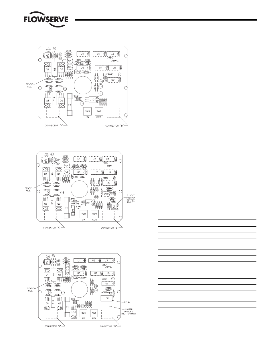
There is only one control that is common to all three versions of
the RTU Interface and that is the current limit adjustment
(I-Limit). This control allows adjustment of the level of load
current that will cause an overcurrent trip.
A second control is found on the version with 0-5 volt position
indication output and is used to adjust for a 5 volt output at the
valve full open position.
D. DC Power Control
The DC power circuitry is 100% solid state and utilizes power
MOSFETS for switching. In addition, DC opto-couplers are used
to isolate the output circuits from the logic and input circuits.
The two circuit board versions with output indication have two
glass envelope fuses for board and motor protection as well as to
protect the power supply in the unlikely event of a board or motor
failure. The smaller fuse protects the circuit board in case of a
logic component failure and the larger fuse protects the power
supply in case of a power MOSFET failure.
IV. INSTALLATION OF RTU INTERFACE
INTO SERIES 75 ELECTRIC
ACTUATOR
A. General
If the actuator was purchased with the RTU Interface board
factory installed, proceed to Section V.
NOTE:
All wiring to terminal strip should be inserted only to mid-point
of terminal strip.
1. Check Kit For Parts:
a. Common Parts For Sizes 10-23:
Qty.
Name
1
Circuit Board Subassembly
1
Insulating Board
5
Washers (Nylon)
5
Grommets (Rubber)
5
Mounting Screws (Circuit Board)
1
Nameplate - Circuit Board
1
Nameplate - Base
1
Wiring Label - Cover
1
Instruction Manual
5
Cable Ties
1
Bracket - Right (Long)
1
Bracket - Left (Short)
4
Spacer (Bracket)
4
Mounting Screw (Bracket/Spacer)
2
Connector Cable Assemblies
(One “A” & One “B” Assembly)
Flow Control
Worcester Actuation Systems
Figure 1: No Output Indication
Figure 2: Position Output Indication
Figure 3: Current Trip Indicator