V. circuit board adjustments, Worcester actuation systems – Flowserve RT92 Series User Manual
Page 6
6
d. Assemble circuit board into actuator. Slide rubber
grommets onto insulating board. Put nylon washers
under heads of self-tapping screws (Five screws will be
used to install the circuit board onto the brackets).
e. Place the circuit board over the brackets with the
insulating board between the circuit board and the
mounting brackets. Loosely tighten the four screws
securing the board and insulator. Use a nylon washer and
a rubber grommet on the self-tapping screw securing the
right front corner of circuit board (as you face the terminal
strip). Place the rubber grommet between the circuit board
and the mounting bracket. Tighten all the mounting screws
so that the grommets are about half compressed.
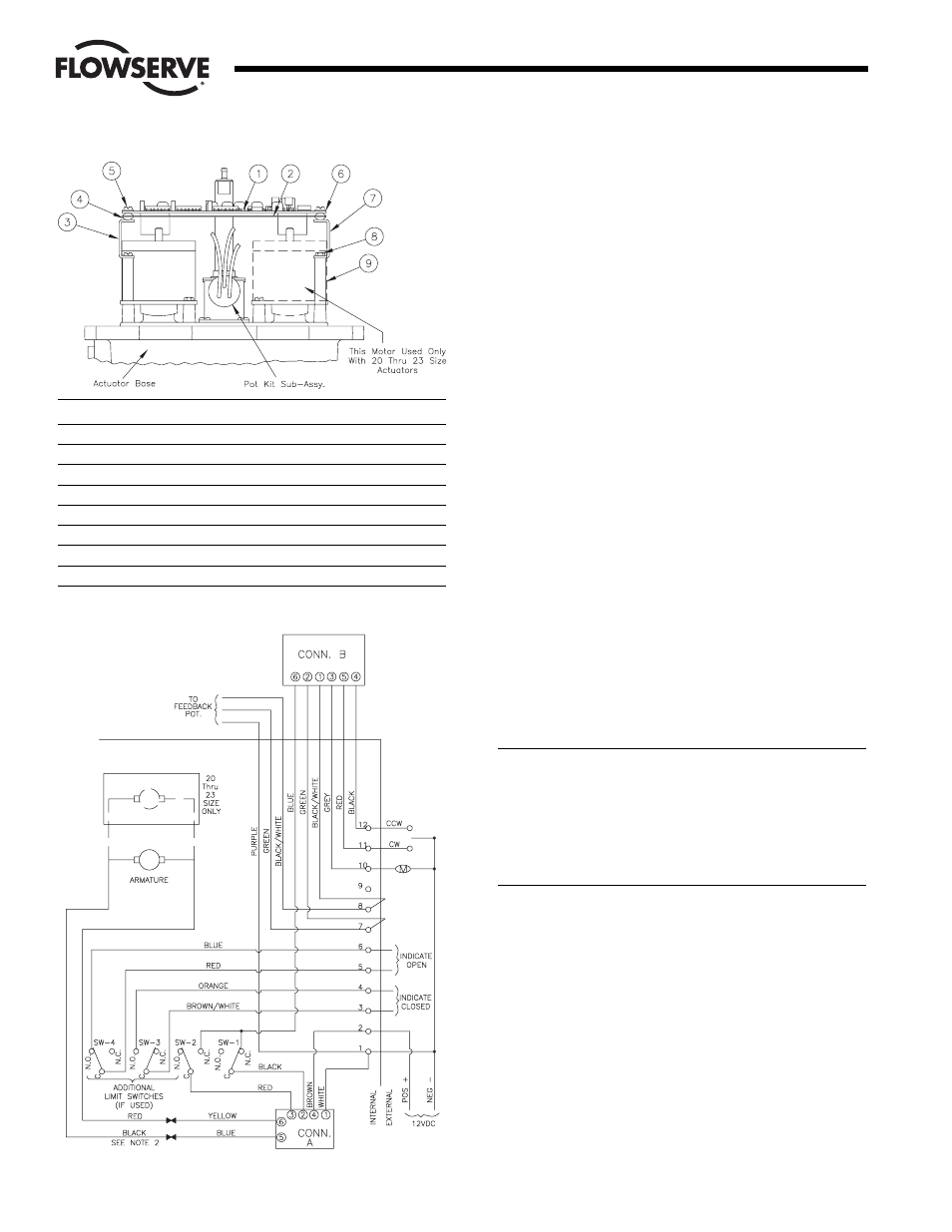
f. Insert each of the cable assembly connectors into its
respective circuit board socket (A and B).
D. Power Connections
The appropriate power source (12 VDC) is connected to terminals
1 (common or negative) and 2 (plus or positive).
NOTES:
1.
Actuator shown in the counterclockwise extreme of travel or
"open" position.
2. For a 10, 20 (motor module on fast side) or 23 75, reverse the
red/black motor leads.
3. Grounding wires should be connected to green colored grounding
screw (if present) on actuator base or to any base plate mounting
screw in the actuator.
For resistive position indication instead of voltage indication,
remove purple wire from terminal #1 and put in rear of terminal
#9. Remove wires from front of terminals #7 and #8 and tape
same.
CAUTION: It is important that the DC voltage power source be
connected properly to the actuator’s terminal strip. Terminal
one (1) of this strip is to have the negative or common wire
connected to it. Terminal two (2) is to have the positive wire
connected to it. The board has a diode and a fuse installed to
prevent damage in the case of reverse voltage polarity, but if
the diode happens to be defective, damage could be done
before the fuse blows.
V. CIRCUIT BOARD ADJUSTMENTS
A. I-Limit Adjustment
1. The RTU card as shipped from the factory should have the
I-Limit pot on the card turned full clockwise. This will allow
the maximum permissable actuator output torque. The
customer can then turn the trimpot counterclockwise in order
to reduce the current trip level. Because of various motor,
gearbox, and voltage combinations possible, different sense
resistor (R8) values are used on the circuit board to allow
operation in a particular current/torque range. The resistor
values are selected as follows:
Flow Control
Worcester Actuation Systems
ITEM
DESCRIPTION
1
Circuit Board Subassembly
2
Insulating Board
3
Bracket-Right (Long)
4
Grommet-Rubber
5
Mounting Screws (Circuit Board)
6
Washer-Nylon
7
Bracket-Left (Short)
8
Mounting Screws (Bracket)
9
Spacer (Bracket)
Figure 5
Figure 6