Flowserve WG Series Limitorque User Manual
Page 8
Limitorque WG Series Worm Gear Operator FCD LMENIM2101-02 – 01/15
8
2.5 Assembly Positions
2.4.2 WG-04 through WG-12
1. Place the valve disk in the full closed position.
2. Remove the Pointer Cap (see Section 4 for removal instructions).
Note: If the Splined Adapter is already installed in the operator, go to step 6.
3. Remove the Retaining Ring and install the Splined Adapter.
Note: The notch in the Worm Gear at the Closed position must be aligned with the keyway in the Splined Adapter.
4. Reinstall the Retaining Ring.
5. Mount the operator on the valve and bolt securely.
6. Rotate the input shaft to align the keyway of the Splined Adapter with the keyway of the Valve Shaft and install the key.
7. Confirm that the gearbox Stop Screws are properly set for valve disk travel in both the Open and Close directions of travel.
See Section 2.6.
8. Reinstall the Pointer Cap.
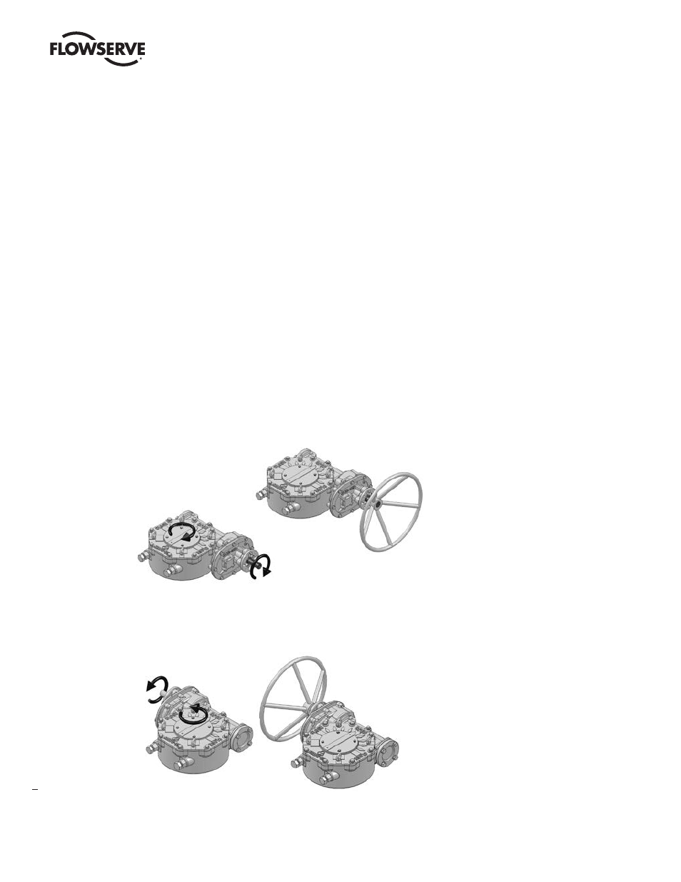
Figure 2.2 – Position A
Figure 2.3 – Position D
STANDARD ASSEMBLY POSITION
Clockwise Input Rotation –
Clockwise Output Rotation
OPTIONAL ASSEMBLY POSITION
Clockwise Input Rotation –
Counterclockwise Output Rotation