2 safety practices, 3 hbc-0 through -3 – Flowserve HBC Series Limitorque User Manual
Page 12
Limitorque HBC Series FCD LMENIM3501-02-AQ – 10/14
12
4.2 Safety Practices
The following checkpoints should be performed to maintain safe operation of the HBC gearbox:
• Set up a periodic operating schedule on infrequently used valves.
• Ensure that the limit and/or torque switches on any electric actuator fitted to the HBC worm
gearbox are correctly and appropriately adjusted.
4.3 HBC-0 through -3
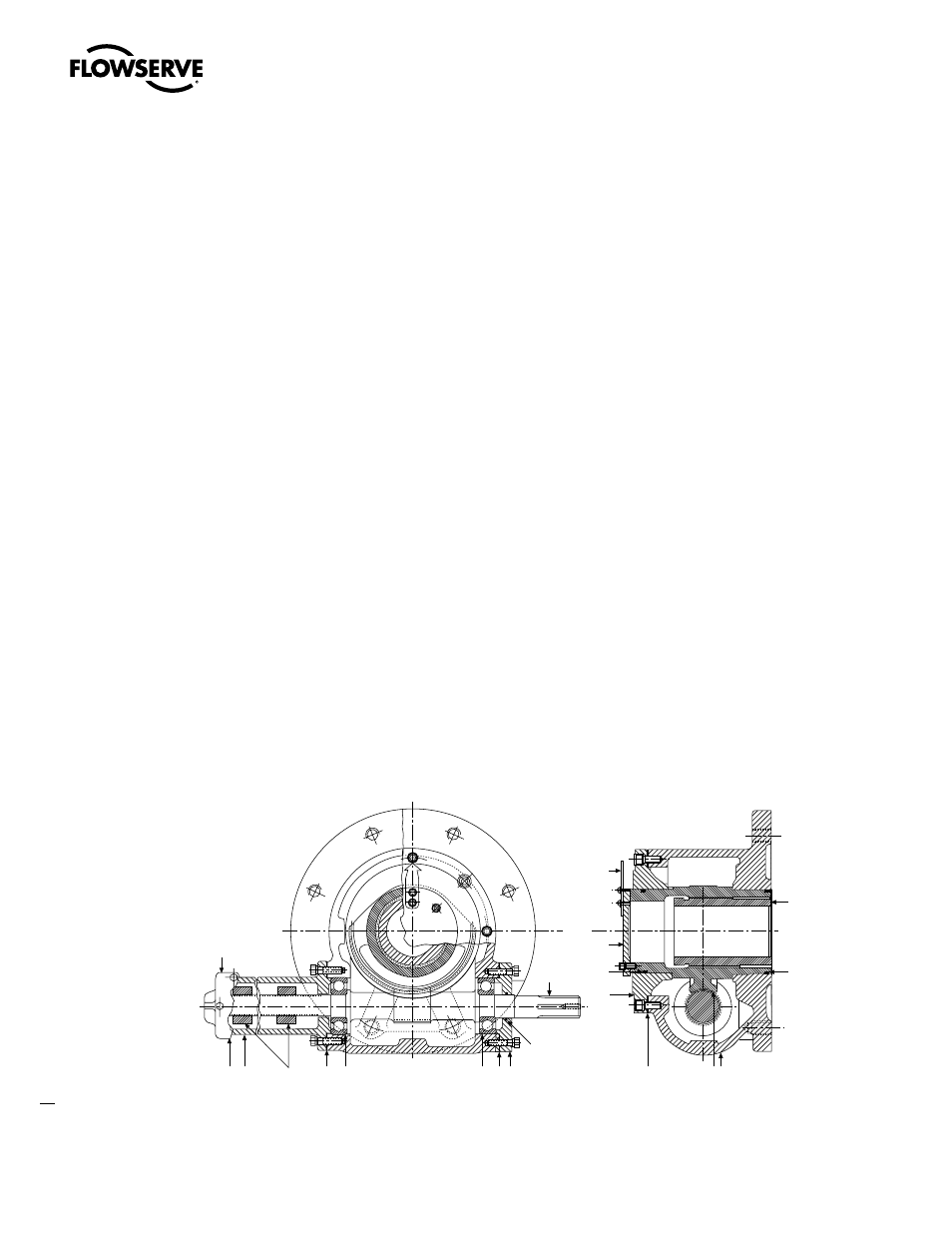
Refer to Figure 4.1.
1. Remove the Limit Stop Housing Cap (piece #20) and Gasket (piece #21).
2. Rotate the Worm Shaft (piece #6) clockwise until Pointer Cap (piece #9) stops rotating.
3. Remove the Pointer Cap (piece #9) and Housing Cover (piece #2).
4. Remove both Stop Nuts (piece #18) and Limit Stop Housing (piece #19).
5. Remove the Through Cap (piece #4).
6. Remove the Worm Shaft (piece #6) by rotating and pulling from Housing (piece #1). It may be necessary to
maneuver the Bearing (piece #13) around the Drive Sleeve (piece #5), by rotating the drive sleeve slightly
in the direction it was turning in Step 2. It is not necessary to remove the Bearing (piece #13) from
Worm Shaft (piece #6).
7. Remove the Drive Sleeve and Worm Gear (piece #5).
NOTE: In reassembling the gearbox, follow all of the above steps in the reverse order. Be sure you have located the
center line of the Worm Gear (piece #5) before reinstalling the Housing Cover (piece #2).
NOTE: For reassembly of the worm shaft (step 6 of the disassembly procedure), be sure that end play does not
exceed 0.015 in. This is accomplished by the proper combination of 0.015 in. and 0.030 in. gaskets on the stop
housing side and input side of the gear housing.
Figure 4.1 – HBC-0 through -3 assembly
20
21 19
18
10 13
13 10 4
15
6
9
2
14
11
5
14
1
7
8