Flowserve HBC Series Limitorque User Manual
Page 7
7
Limitorque HBC Series FCD LMENIM3501-02-AQ – 10/14
flowserve.com
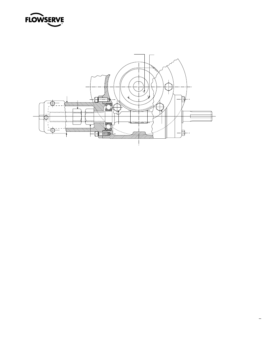
Figure 2.3 – Hex nut type stop (HBC-0 through -3)
Index mark
on drive sleeve
Two index marks appear
on housing cover
Hex nut “B”
Cover plate
Bolt “C”
Bolt “D”
Hex nut “A”
Limit stop
housing
Max Travel
2.6 Setting Position Limit Stops for HBC-4 through -7
Refer to Figure 4.2.
1. With the valve in the full closed position, remove Stop Screw Cover (piece #16).
2. Remove the Lock Screw (piece #17).
3. Adjust the appropriate Stop Screw (piece #17) based on rotation of the drive sleeve — inward if valve is closed
and stop has not yet been reached, or outward if stop has been reached and valve is not yet fully closed.
4. Once the Stop Screw is set, lock securely with Lock Screw.
5. Operate the valve to fully open position and set open stop in the same manner.