7 hbc angular displacement tolerances – Flowserve HBC Series Limitorque User Manual
Page 8
Limitorque HBC Series FCD LMENIM3501-02-AQ – 10/14
8
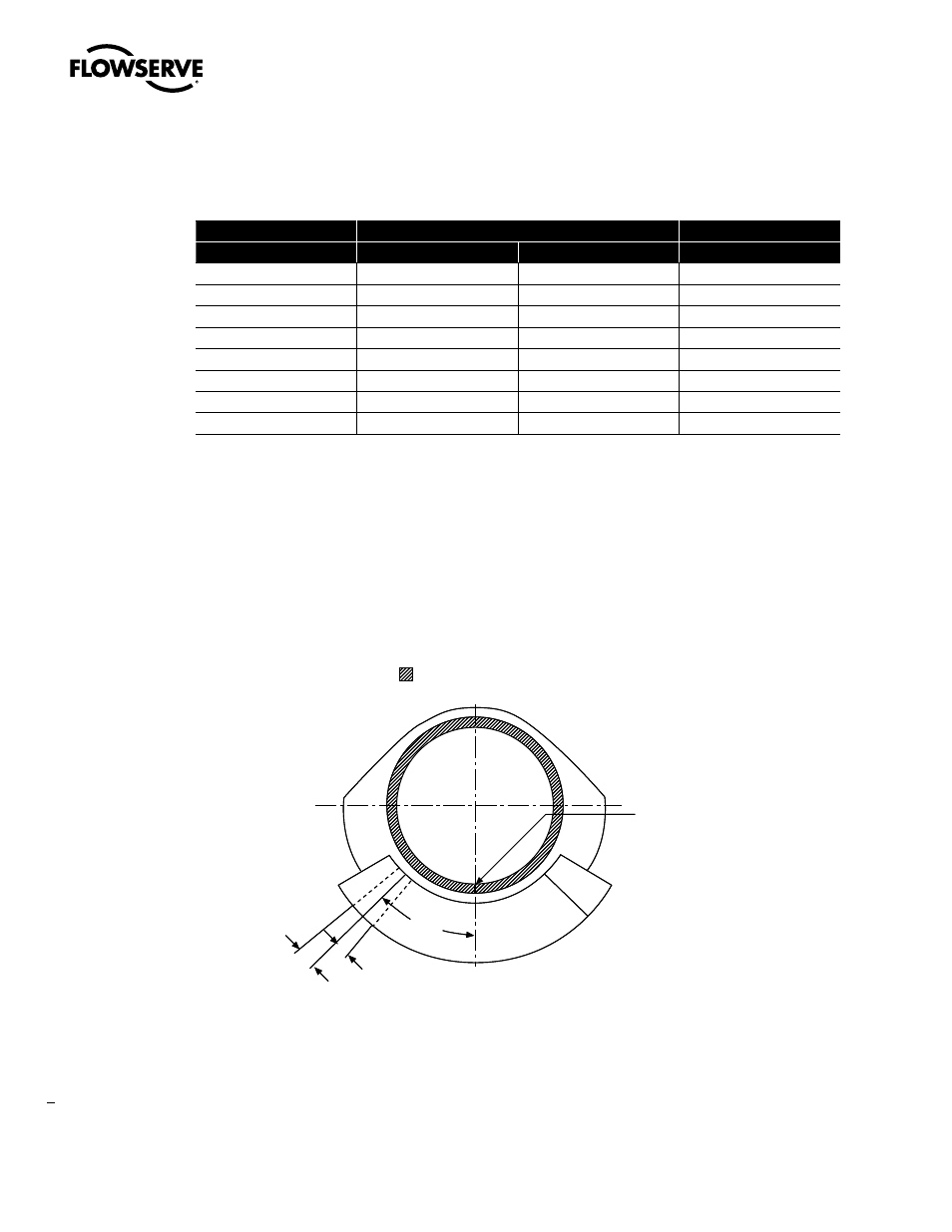
Top of drive sleeve with
pointer cap removed
Worm gear
Index mark at
midpoint of
available
rotation
Plus
tolerance
45ϒ
Minus
tolerance
Top of drive sleeve with
pointer cap removed
Worm gear
Index mark at
midpoint of
available
rotation
Plus
tolerance
45ϒ
Minus
tolerance
Figure 2.4 – Top of drive sleeve showing available rotation
2.7 HBC Angular Displacement Tolerances
Table 2.1 – HBC angular displacement tolerance
Angular Displacement
Splined Tooth
Gearbox Size
Stop
Gear
Space in Degrees
HBC-0
105°
1
170° Gear Segment
9.00°
HBC-1
114°
1
170° Gear Segment
6.42°
HBC-2
114°
1
170° Gear Segment
4.50°
HBC-3
114°
1
170° Gear Segment
3
3.46°
HBC-4
±7°
2
±7°
3.00°
HBC-5
±6.75°
2
±6.75°
2.14°
HBC-6
±9°
2
±9°
1.80°
HBC-7
±9°
2
±9
N/A
Note 1: Stops used on HBC-0 through HBC-3 incorporate standard hex nuts. The tolerance listed is ±0.31 from basic size on the
thickness. The data shown above is based on maximum thickness of both nuts.
Note 2: Displacement is based on 45° travel on either side of gear centerline.
Note 3: Gearboxes with serial numbers less than S/N 365365 have 110° gear segments.