Flowserve Supplement 2 75 DeviceNet PLC User Manual
Supplement 2 75 devicenet plc, Installation, operation and maintenance
Supplement 2
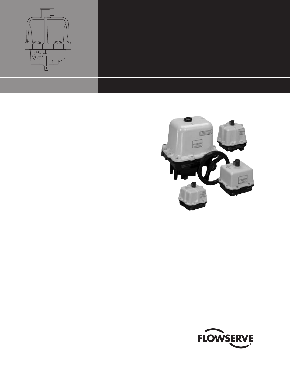
75 DeviceNet PLC
Installation, Operation and Maintenance
FCD WCAIM2062-00 (Part 14142)
Test and Operation Example
Using an Allen Bradley SLC-
Programmable Logic Controller
Assumption: working knowledge of Allen Bradley SLC processor
and software
a
CAUTION: The PLC/Process Controller logic should never
set bits 5 and 6 on (1) at the same time in output word 1.
These bits control actuator CCW and CW rotation and dam-
age to the relay interface module and motors will result if
these bits are set on (1) simultaneously. The output word 1
corresponds to an actuator at Address 1.
Hardware and Software Used
in this Example
WORCESTER CONTROLS
• 75 Actuator with Integral DeviceNet Interface Module
• Computer Disk of Electronic Data Sheet (.eds)—Supplied with
ACCESS Actuator
ALLEN BRADLEY
• SLC-503—Processor
• Four Slot Rack
• P2 Power Supply
• DeviceNet Scanner Module 1747-SDN (located in slot 4)
• KF2-RS-232—Communication Interface Module
Flowserve Worcester Control Series 75 Actuators
• PC to Processor Cable—1747-CP3
• RS LOGIC Software
• RS LINX Software
• RS Networx for DeviceNet Software
• PC to SLC/PLC Cable—1747-CP3
OTHER
• Regulated—24 VDC Power Supply
• DeviceNet System of Cables and Connectors
• 120 ohm Network Terminating Resistors
���������������������������